
Note. A description of the procedures for removing and installing mounting blocks combined with SAM modules is given in Section Removing and installing control modules.
Main fuse box (on the left under the instrument panel)
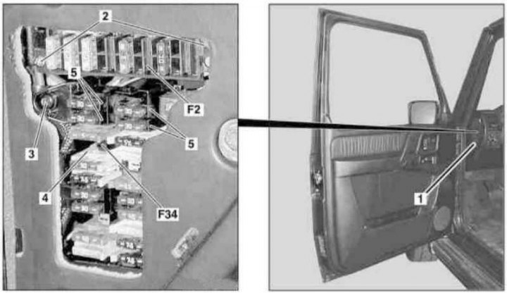
Installation details of the main fuse box (1 of 2)
1 - Left side cover; 2, 3 - Bolts; 4 - Fuse holder; 5 - Receiving nests; F2 - Mounting block for 8 fuses; F34 - Cabin mounting block
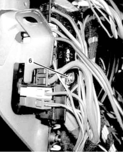
Installation details of the main fuse box (2 of 2)
6 - Locknut
1. On models of the corresponding configuration (code ET2) activate the service mode of the TELE AID emergency call system (see Section Activation / deactivation of the service mode of the TELE AID emergency call system).
2. Disconnect the negative cable from the battery.
3. Remove the left side cover from the instrument panel (1).
4. Release the clips securing the holder (4) fuses in the mounting block (F34), - do not forget to pre-mark the installation position of the components.
5. Remove from the mounting block (F34) remaining fuses.
6. Carefully release the latches and remove from the mounting block (F34) receiving nests (5).
Explanations for disconnecting from wiring mount blocks are given in Section Disconnecting and connecting wiring of mounting blocks and control modules.
7. Turn out bolts (2) mounting block fasteners (F34).
8. Loosen locknut (6) from the back of the block (F34) and disconnect from the last wiring circuit 30), - when installing, the locknut must be replaced.
9. Remove the mounting block (F34).
10. Turn out bolts (3) and remove the mounting block (F2) for 8 fuses.
11. Installation is carried out in the reverse order, - with the appropriate configuration (code ET2) deactivate the service mode of the TELE AID system (see Section Activation / deactivation of the service mode of the TELE AID emergency call system).
12. Finally, read the DTCs and clear the OBD memory using the STAR DIAGNOSIS scanner (6511 1801 00) (see chapter Engine Electrical Systems).
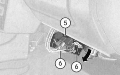
Mounting block installed in the right front footwell
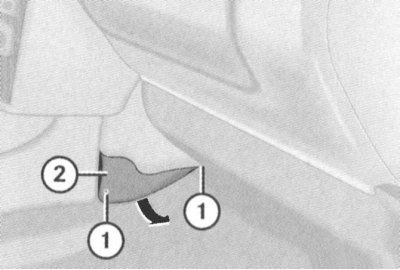
1. Remove the fixing screws (1) and pulling in the direction indicated by the arrow, remove the cover (2) on the left under the instrument panel.
2. Remove the screws (3) and, pulling in the direction indicated by the arrows, remove the cover (4).
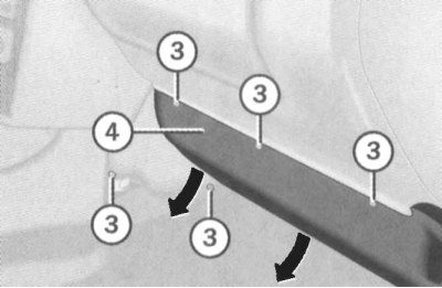
3. Remove the screws (6), release the mounting block (5) out of its seat and lower it down to gain access to the fuses.
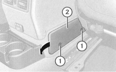
Mounting block installed in the rear of the center console
1. On Wagon models with a long base, pry off with a screwdriver, remove the stop brackets installed in front of the right front seat sled.
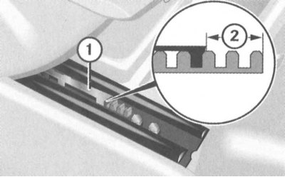
1 - Stop bracket
2 - Nominal shackle installation distance
Note. When installing the brackets must be planted strictly in a certain position at a distance (2) from the edge of the slope.
2. Move the right seat forward until it stops.
3. Remove the fixing screws (1) and pulling in the direction indicated by the arrow, remove the cover (2) behind on the right wall of the console assembly.
Mounting block that fits in a box for installing a battery
The mounting block is placed under the cover in the rear footwell. The fuses included in the block do not, as a rule, need to be replaced, and in the event of their failure, you should seek help from the specialists of the Mercedes-Benz branded service station.
Relay holder in luggage compartment
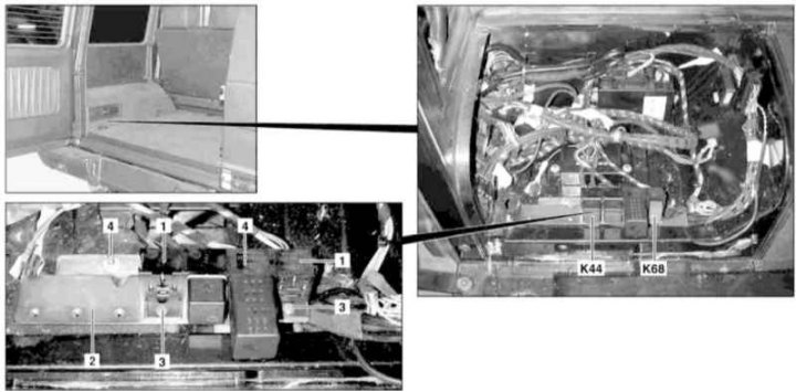
Installation details of the relay holder in the luggage compartment
1 - Receiving sockets; 2 - Relay holder; 3 - Bolts; 4 - Nuts; K44 - Single lock relay; K68 - Rear wiper relay
1. Turn on the auxiliary battery and connect it to the standard battery, then disconnect the negative cable from the latter.
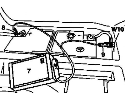
7 - Auxiliary battery
8 - Module positive wire terminal
9 - Terminal of the negative wire of the module
W10 - Battery Ground
2. Remove the CD changer on eligible models (code EP5) /TV tuner (code EM9) (see Section Removing and installing CD changer/TV tuner).
3. Remove from receptacles (1) single lock relay (K44) and rear wiper (K68).
4. Release fastener (3 and 4) and remove the relay holder (2).
5. Installation is carried out in the reverse order.
6. Finally, read the DTCs and clear the OBD memory using the STAR DIAGNOSIS scanner (6511 1801 00) (see chapter Engine Electrical Systems).