



CD changer (equipment code EP5)
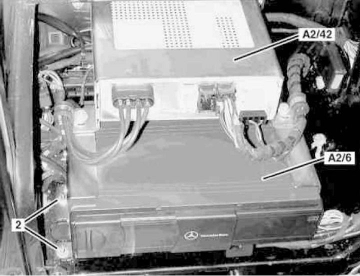
CD changer installation details using the example of the Universal models (1 of 2)
2 - Fastening nuts; A2/6 - CD changer; A2/42 - TV tuner
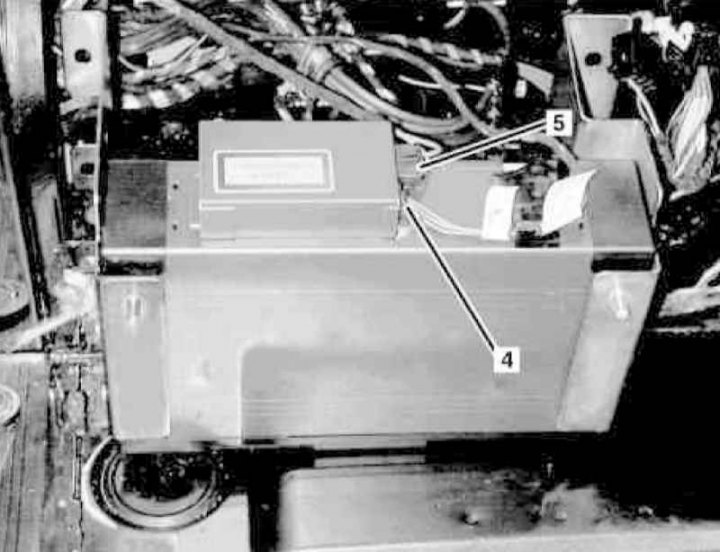
CD changer installation details using the example of the Universal models (2 of 2)
4 - CD changer power supply harness connector; 5 - Fiber optic cable connector
1. Remove the magazine from the CD changer.
2. Turn on the auxiliary battery and connect it to the standard battery, then disconnect the negative cable from the latter.
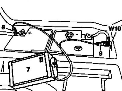
7 - Auxiliary battery
8 — Positive wire terminal of the module
9 — Terminal of the negative wire of the module
W10 - Battery ground
3. On models with the corresponding configuration (code EM9), remove the TV tuner (A2/42) (see below).
4. Loosen the four mounting nuts (2), disconnect the connectors (4 and 5) on the rear side of the CD changer assembly (A2/6) and remove the latter.
Note: Immediately seal the waveguides of the fiber optic cable connection connector (5) with special light-proof caps.
5. Installation is carried out in reverse order.
6. Finally, read the DTC codes and clear the on-board diagnostic system memory using the STAR DIAGNOSIS scanner (6511 1801 00) (See Chapter Engine electrical systems) and perform basic programming procedures.
TV tuner (assembly code EM9)
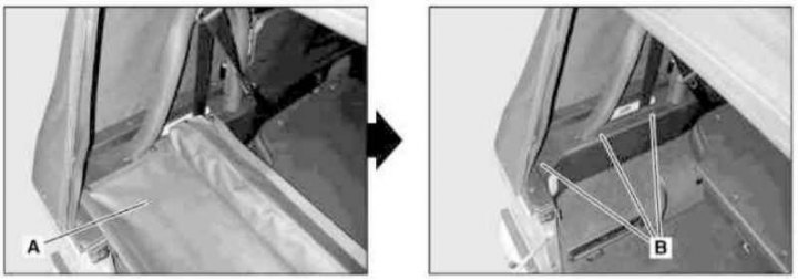
TV Tuner Installation Details (1 of 2)
A - Cover equipped with a wind deflector
B — Wind deflector support
TV Tuner Installation Details (2 of 2)
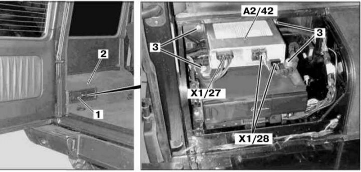
1 - Plastic frame for installing a CD changer; 2 - Carpet panel; 3 - Mounting screws; A2/42 - TV tuner; X1/27 - Antenna connector; X1/28 - Electrical wiring connector
1. On models with the corresponding configuration (code ET2), activate the service mode of the TELE AID emergency call system (see Section Activation/deactivation of the service mode of the TELE AID emergency call system).
2. Turn on the auxiliary battery and connect it to the standard battery, then disconnect the negative cable from the latter.
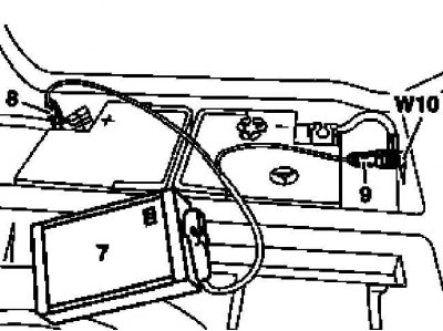
7 - Auxiliary battery
8 — Positive wire terminal of the module
9 — Terminal of the negative wire of the module
W10 - Battery ground
3. On models with the corresponding equipment (code V57), remove the luggage compartment lid.
4. Remove the wind deflector equipped cover (A) - three push-button fasteners on each side.
5. Remove the left wind deflector support bracket (B).
6. On models with the corresponding equipment (code V53), remove the left storage compartment.
7. On models with the corresponding configuration (code EP5), remove the plastic frame (1) for installing the CD changer (see above).
8. Slightly lift the side trim panel and remove the carpet trim (2) from the left wheel arch.
9. Remove the two mounting screws and remove the adjacent floor carpet panel.
10. Disconnect the antenna cable connectors (X1/27) and electrical wiring (X1/28).
11. Remove the four mounting screws (3) and remove the TV tuner (A2/42).
12. Installation is carried out in the reverse order - on models with the corresponding configuration (code ET2) deactivate the service mode of the TELE AID system (see Section Activation/deactivation of the service mode of the TELE AID emergency call system).
13. Finally, read the DTC codes and clear the on-board diagnostic system memory using the STAR DIAGNOSIS scanner (6511 1801 00) (See Chapter Engine electrical systems).