
Rooftop cell phone antenna (PR number EV5)
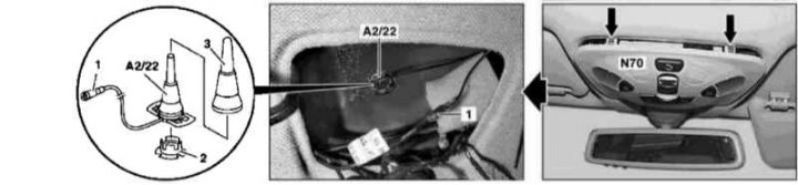
Installation Details of a Fixed Cell Phone Antenna (PR number EV5)
1 - Connector; 2 - Retainer; 3 - Protective cover; A2/22 - Antenna; N70 - Overhead console panel
1. Turn on the auxiliary battery and connect it to the standard battery, then disconnect the negative cable from the latter.
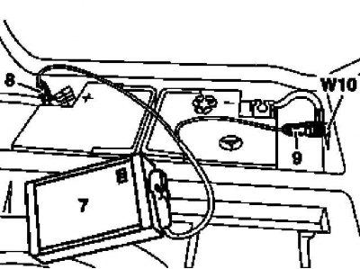
7 - Auxiliary battery
8 - Module positive wire terminal
9 - Terminal of the negative wire of the module
W10 - Battery Ground
2. Remove the overhead console panel (N70) (see Section Removal and installation of the panel of the ceiling console).
3. Disconnect the connector (1) top telephone antenna wiring (A2/22).
4. Remove the retainer (2).
5. Remove the protective cover (3), then using a special puller (210 589 04 33 00) release and remove the antenna assembly (A2/22).
6. Installation is carried out in the reverse order - to fit the protective cover (3) a special mandrel is used (210 589 05 33 00).
7. Finally, read the DTCs and clear the OBD memory using the STAR DIAGNOSIS scanner (6511 1801 00) (see chapter Engine Electrical Systems).
Outdoor radio/cell phone antenna (Convertible models)
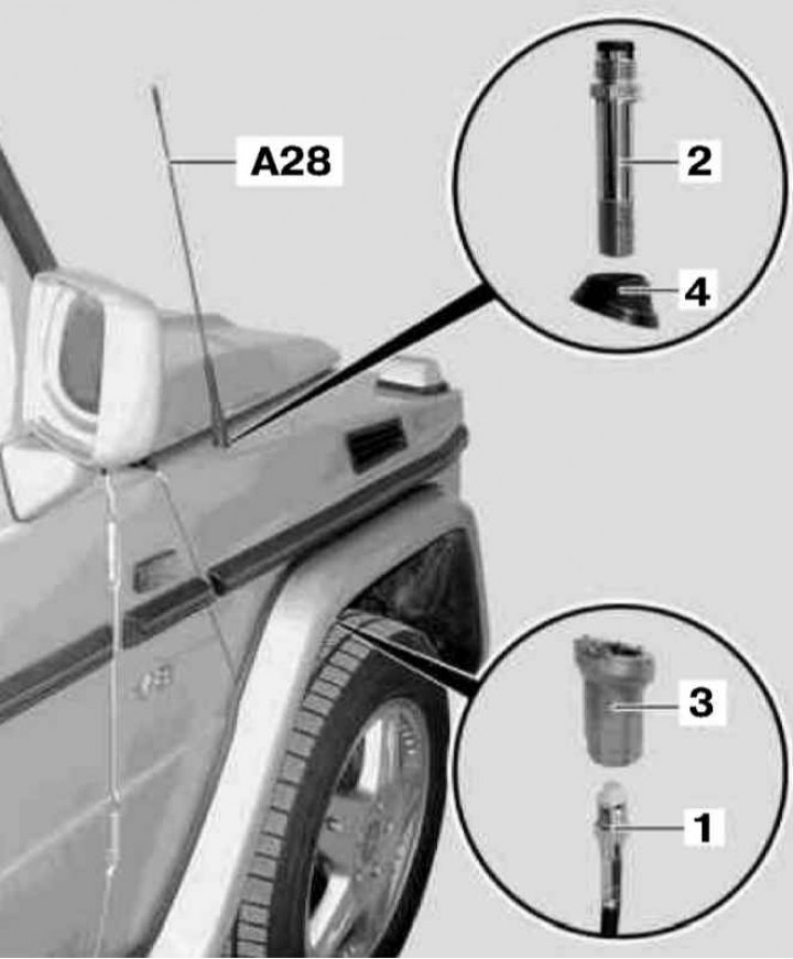
Installation details of the outdoor antenna assembly on the corresponding configuration Convertible models (codes EF1÷EF4 and EF7)
1 - Antenna cable; 2 - Screw; 3 - Nut; 4 - Holder; A28 - Antenna node
The antenna assembly discussed here is used on Convertible models equipped with Audio 10/30 RDS audio systems and Handsfree for Nokia 6210 portable phones (PR codes EF1 ÷ EF4 and EF7).
1. Unscrew the antenna assembly (A28).
2. Remove the right front wheel arch protection locker.
3. Turn out a steering wheel against the stop to the right.
4. Using a wrench, disconnect the antenna cable through the wheel arch (1) by screws (2).
5. Locking the nut from below (3), remove the screw (2).
6. Remove the holder (4) and a nut (3).
7. Installation is carried out in the reverse order.
Front Global Positioning System Antenna (GPS)
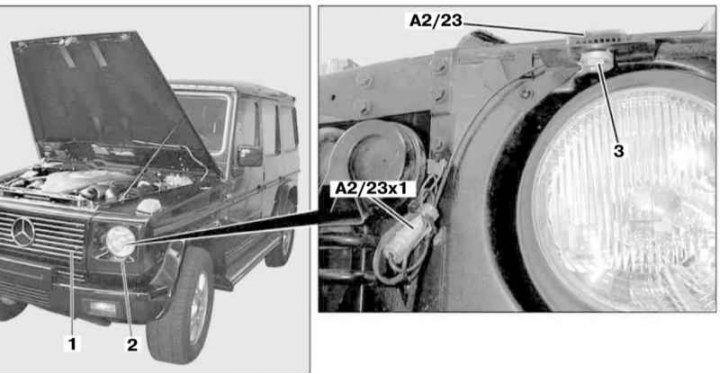
Installation Details of GPS Navigation System Antenna
1 - Front grille; 2 - Headlight cover; 3 - Fixing nut; A2/23x1 - GPS connector; A2/23 - GPS Antenna
1. Remove the front grill (1) and facing cover (2) left block headlight (see chapter Body).
2. Disconnect the connector (А2/23x1).
3. Loosen the fixing nut (3) and remove the antenna assembly (A2/23).
4. Installation is carried out in the reverse order.