



Contents: Front door lock actuators ↡ Rear Door Lock Activators ↡ Tailgate Lock Activator (convertible…↡ Fuel filler flap lock actuator ↡
Front door lock actuators
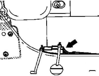
Front Door Lock Actuator Installation Details (1 of 3)
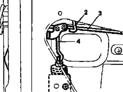
Front Door Lock Actuator Installation Details (2 of 3)
4 — Drive rod
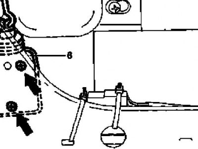
Front Door Lock Actuator Installation Details (3 of 3)
6 — Drive electric motor
1. Disconnect the negative cable from the battery.
2. Remove the door interior trim panel (see Chapter Body).
3. Disconnect the electrical connector (arrow) from the door lock actuator.
4. Disconnect the drive rod from the door lock.
5. Loosen the mounting screws and remove the actuator motor assembly (6).
6. Installation is carried out in the reverse order - make sure that the electrical wiring is laid correctly and that the connector is securely fixed.
Rear Door Lock Activators
Models Universal
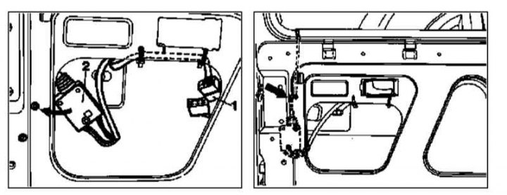
Rear Door Lock Actuator Installation Details (models Universal)
1 - Electrical wiring connector
2 - Drive electric motor
1. On models with the corresponding configuration (code ET2), activate the service mode of the TELE AID emergency call system (see Section Activation/deactivation of the service mode of the TELE AID emergency call system).
2. Disconnect the negative cable from the battery.
3. Remove the door interior trim panel (see Chapter Body).
4. Release the single lock wiring harness from the door assembly and disconnect the connector (1).
5. Disconnect the drive rod (arrow) from the door lock.
6. Loosen the fasteners and remove the drive motor (2).
7. Installation is carried out in the reverse order - make sure that the electrical wiring is laid correctly and that the connector is securely fixed.
8. On models with the corresponding configuration (code ET2), deactivate the service mode of the TELE AID system (see Section Activation/deactivation of the service mode of the TELE AID emergency call system).
9. Finally, read the DTC codes and clear the on-board diagnostic system memory using the STAR DIAGNOSIS scanner (6511 1801 00) (See Chapter Engine electrical systems) and perform basic programming procedures.
Models with a wheelbase of 2850 mm
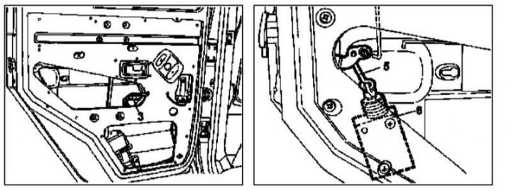
Rear Door Lock Actuator Installation Details (models with a base of 2850 mm)
3 - Electrical wiring connector; 5 - Drive rod; 6 - Drive electric motor
The procedure is the same as described above for the front door actuator (see paragraphs 1 through 6).
Tailgate Lock Activator (convertible models)
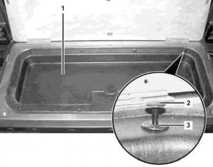
Tailgate Lock Actuator Installation Details on Convertible Models (1 of 2)
1 - Plastic tray; 2 - Plastic retainer; 3 - Expander pin
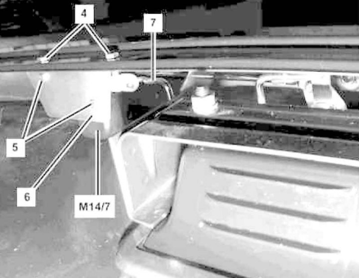
Tailgate Lock Actuator Installation Details on Convertible Models (2 of 2)
4, 5 - Screws; 6 - Mounting bracket; 7 - Drive rod; M14/7 - Drive electric motor
1. Fold back the tailgate and remove the tool compartment cover from the rear side.
2. Pry up the fasteners (2), remove the expansion pins (3) and remove the plastic tray of the tool compartment.
3. Disconnect the electrical wiring from the drive motor (M14/7) of the single lock.
4. Separate the drive rod from the electric motor (M14/7) - the rod remains connected to the lock assembly.
5. Unscrew the fastening screws (5) and remove the mounting bracket (6) from the electric motor assembly (M14/7).
6. Remove the electric motor (M14/7).
7. Installation is carried out in reverse order.
Fuel filler flap lock actuator
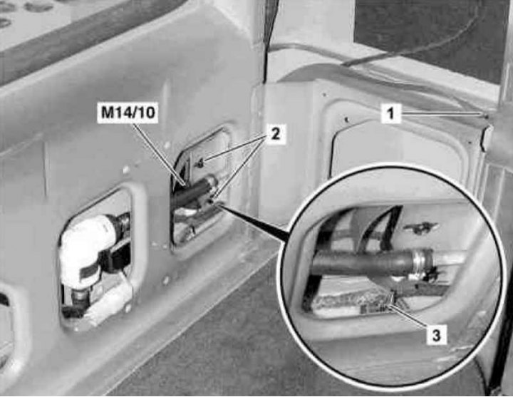
Fuel filler flap lock actuator installation details
1, 2 - Screws; 3 - Locking pin; M14/10 - Drive electric motor
1. Remove the right rear section of the side trim (see Chapter Body).
2. On Station Wagon models, remove the screw (1) of the emergency release tension strap of the filler flap.
3. Unscrew the screws (2), having first marked the positions of their heads in the oval holes.
4. Release the locking pin (3) from the guide.
5. Tilt backwards and remove the drive motor (M14/10).
6. On Convertible models, disconnect the emergency release rod from the lock pin (3).
7. Disconnect the electrical wiring from the motor (M14/10).
8. Installation is carried out in the reverse order - make sure that the marks applied during dismantling are correctly aligned (see paragraph 2).