
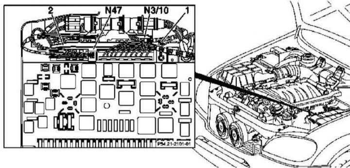
Details of installation of control modules in the main mounting block
Fuel injection control module (ECM/ME-SFI)
1. If the ECM is to be replaced, read its coding using a special diagnostic scanner (see chapter Engine Electrical Systems).
2. Remove the five fixing screws and remove the back cover of the main mounting block.
3. Disconnect wiring from ME-SFI control modules (N3/10) and ETS/ESP (N47).
4. Remove the fixing screws (1) and remove the control module assembly with the installation frame (2).
5. Turn out fixing screws/release clamps and remove ECM (N3/10) from the frame (2).
6. Installation is carried out in the reverse order.
7. When installing a new module, code it using a diagnostic scanner.
8. To enter data on the idle position of the throttle into the memory of the module, turn the key in the ignition switch to position 2 and wait 60 seconds.
Traction Control Module (ETS/ESP)
1. Remove the back cover of the main mounting block.
2. Disconnect the wiring and pull up to remove the ETS/ESP module (N47).
3. Installation is carried out in the reverse order. Finally, check that the coding of the brake system is correct.
General activity module (AAM)
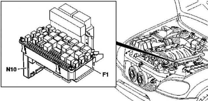
General activity module installation details (AAM)
1. Details of installing the AAM module are shown in the illustration, to which all references in the text refer.
2. If the AAM module is to be replaced, read its coding using a special diagnostic scanner (see chapter Engine Electrical Systems).
3. Remove the covers of the main mounting block in the engine compartment (see Section Removal and installation of mounting blocks).
4. Remove the two mounting bolts and remove the fuse and relay module (F1) main mounting block.
5. Carefully detach from the AAM (N10) electrical wiring and a bi-directional radio antenna.
6. Carefully separate the AAM module from the assembly (F1). Try not to bend the contact terminals - the connector latches are located at the top edge of the flat area in the central part of the module.
7. Installation is carried out in the reverse order - when installing a new module, do not forget to encode it using a diagnostic scanner.
Extended activity module (EAM)
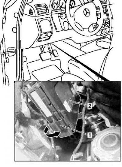
Installation Details of Extended Activity Module (EAM)
1. The details of installing the EAM module are shown in the illustration, to which all references in the text refer.
2. If the EAM module is to be replaced, read its coding using a special diagnostic scanner (see chapter Engine Electrical Systems).
3. Remove the cover on the left under the instrument panel (see chapter Body).
4. Release the lock (1) mounting the EAM module (2) on the base bracket.
5. Pull down to remove the EAM (2) from the support bracket.
6. Disunite contact sockets of electroconducting.
7. If necessary, remove the driver authorization module (FBM/DAS) (see below).
8. Installation is carried out in the reverse order - when installing a new module, do not forget to encode it using a diagnostic scanner.
Driver authorization control module (FBM)
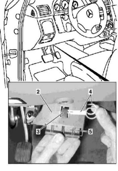
Driver authorization control module installation details (FBM/DAS)
4 - Devices for removing the module
1. FBM/DAS installation details are shown in the illustration, to which all references in the text refer.
2. Remove the extended activity module (EAM) (2) (see above).
3. Release the latches (3) and separate FBM/DAS (5) from the EAM module.
Note. Before replacing the FBM/DAS module, check whether the keys have been authorized and make sure that the coding matches the replacement unit - a new module is ordered based on the vehicle's chassis number.
4. Installation is carried out in the reverse order.
5. Having finished installation, check up serviceability of start of the engine by keys.
Additional security control module (SRS)
SRS control module installation details
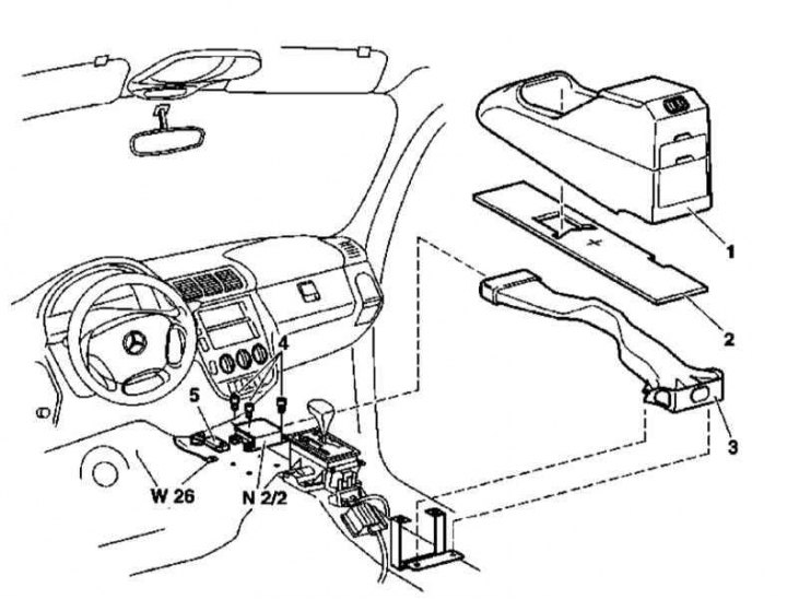
1. This module provides control of the deployment of airbags, as well as emergency pretensioners for the front seats. The details of installing the SRS control module are shown in the illustration, to which all references in the text refer.
2. In order to prevent a fault code from being written to the memory of the control module (DTC) turn the ignition key to position 0.
3. Disconnect the negative cable from the battery.
4. Remove the center console (1) (see chapter Body).
5. Depending on the equipment, remove the soundproof panel (2) / lift its front edge.
6. If equipped, remove the two rear mounting screws and remove the heating/ventilation/air conditioning duct (3).
7. Disconnect the wiring connector (5) SRS control module (N2/2).
8. Remove the fixing screws (4) and remove the SRS control module (N2/2) from the transmission tunnel.
9. Installation is carried out in the reverse order - the arrow printed on the module body must point in the direction of vehicle movement. Do not forget to place a ground terminal under the left rear module fastening screw (W26).
10. Finally, program and parameterise the new SRS control module.
Emergency call system control module (E-call)
Installation details of the emergency call system control module (E-call)
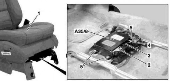
1. Installation details of the emergency call system control module (E-call) illustrations are shown, to which all references in the text refer.
2. Remove the F8 fuse in the fuse/relay mounting block.
3. Remove the screws on the right front seat console (1).
4. Tilt the seat assembly back all the way into the rear seat cushion and secure it in this position with the rear seat belt. Release the E-call speaker harness from its support bracket and cover the floor carpet behind the front seat assembly to prevent contamination.
5. Disconnect the electrical wiring connector (2) and antenna connector (4) on the assembly of the E-call module (А35/8), - do not bend or pull out the fiber optic cable, immediately install protective caps on the connectors.
6. Remove the fixing screws (5) and remove the E-call control module (А35/8).
7. Installation is carried out in the reverse order.
Front seat adjustment control modules
Socket of the e/motor of adjustment of height of position of back edge of a pillow of a seat
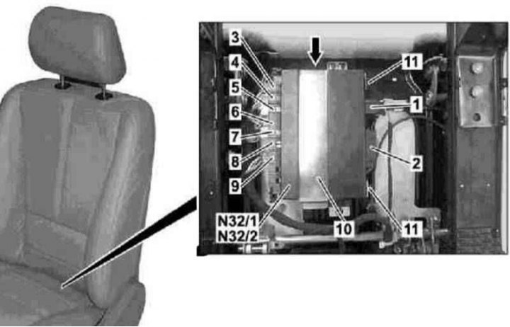
4 - Connector for the e / motor for adjusting the position of the seat in the horizontal plane; 5 - Connector for the e / motor for adjusting the height of the position of the front edge of the seat cushion; 6 - Connector for the electrical wiring of the seat belt buckle; 7 - Connector for the e / motor for adjusting the backrest; 8 - Wiring connector for the child seat installation registration system (for passenger seat); 9 - Seat heating connector
1. The installation details of the front seat adjustment control modules are shown in the illustration, to which all references in the text refer.
2. Slide the seat assembly all the way forward and lift the rear edge of the cushion to the extreme position.
3. Disconnect the connector of the actuator switches (1), as well as a connector for the cabin wiring harness (2) on the seat adjustment control module (N32/1 or N32/2).
4. Turn out a fixing bolt (arrow) and remove the support bracket (10).
5. Release the latches (11), disconnect the electrical wiring and remove the control module (N32/1 or N32/2) from the seat frame.
6. Installation is carried out in the reverse order.
7. In conclusion, check the correct functioning of the seat adjustment drive and the function of entering the selected position into the module memory.
Control module for adjusting the direction of the optical axes of the headlights
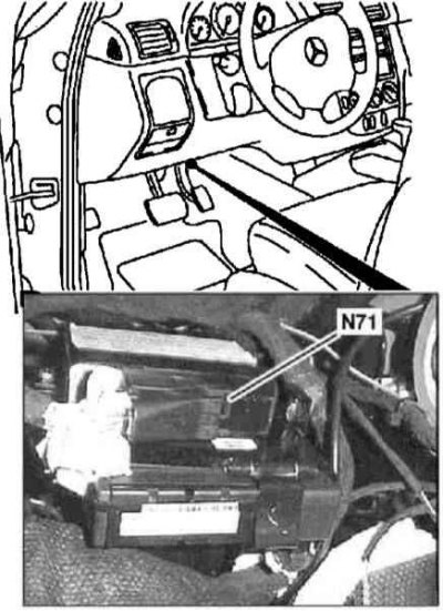
Details of installation of the control module for adjusting the direction of the optical axes of the headlights (N71)
1. Details of the installation of the control module for adjusting the direction of the optical axes of the headlights are shown in the illustration, to which all references in the text refer.
2. Remove the cover on the left under the instrument panel (see chapter Body).
3. Disconnect from the headlamp leveling module (N71) wiring.
4. Give two fixing nuts and remove the module (N47) from the base of the general activity module (EAM) (see above).
5. Installation is carried out in the reverse order.
6. In conclusion, using a diagnostic scanner (see chapter Engine Electrical Systems) reset the headlights, then make any necessary adjustments.
Xenon headlight control module
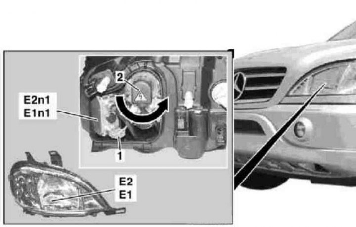
Xenon headlight control module installation details
1. Installation details of the xenon headlight control module are shown in the illustration, to which all references in the text refer.
2. Remove the corresponding headlamp (E1 or E2) (see Section Removal and installation of block headlights, replacement of lamps).
3. Remove the back cover of the headlamp.
4. Turning counterclockwise, disconnect the electrical wiring connector (1 or 2) corresponding control module (E1n1 or E2n1).
5. Remove the control module (E1n1 or E2n1), gently squeezing it out of the support with a suitable wedge.
6. Installation is carried out in the reverse order.
7. In conclusion, using a diagnostic scanner (see chapter Engine Electrical Systems) reset the headlights, then make any necessary adjustments.
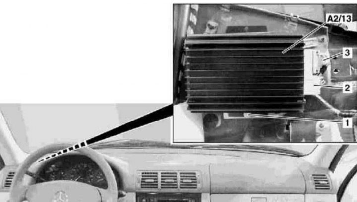
Loudspeaker Amplifier Control Module
Xenon headlight control module installation details
1 - Bolt
2, 3 - Electrical wiring connectors
A2 / 13 - Sound amplifier
1. The installation details of the loudspeaker amplifier control module are shown in the illustration, to which all references in the text refer.
2. Remove the cover on the left under the instrument panel (see chapter Body).
3. Remove the screw (1) and remove the audio amplifier (A2/13) from the support bracket, - set aside the insulation.
4. Disconnect the electrical wiring connectors (2 and 3), - on models with VIN A289565, X754620, one connector is used.
5. Disconnect the D2B connector, - do not bend or pull out the fiber optic cable, immediately install the protective caps on the connectors.
6. Remove the sound amplifier (A2/13), - take care not to damage the wiring.
7. Installation is carried out in the reverse order.