
Removing
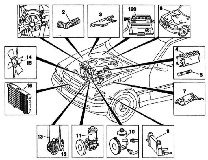
1 - Delivery pump; 2 - Inlet pipe; 3, 7 - Decorative panels; 4 - Air cleaner cover; 5 - Air inlet pipe; 6 - Engine wiring; 9 - Oil cooler; 10 - Power steering pump 11 - Dual pump; 12 - Air conditioning compressor; 13 - Generator drive belt; 14 - Fan; 15 - Fan clutch; 16 - Radiator; 120 - Battery
1. Remove the bottom motor guard.
2. Disconnect the exhaust system.
3. Disconnect the negative cable from the battery (120).
4. Disconnect the air inlet pipe (5).
5. Remove the air cleaner cover (4).
6. Remove decorative panels (3) And (7).
7. Disconnect the nozzle (2) from the turbocharger.
8. Turn away tubes АТ from clamps.
9. Disconnect a longitudinal rack and the bridge.
10. Disconnect the hood cable.
11. Remove the radiator (16).
12. Loosen the pipes of the cooling system between the engine and the body and disconnect them.
13. Remove the fan (14).
14. Remove fan clutch (15).
15. Remove the alternator drive belt (13).
16. Remove the air conditioning compressor (12).
17. Disconnect the electrical wiring between the engine and the body.
18. Disconnect the wiring connectors from the pressure and oil level sensors.
19. Disconnect the starter wiring.
20. Remove the engine wiring.
21. Remove fluid from the pump reservoir (10) power steering.
22. Disconnect the charge pump (1) or double pump (11) and pipes between the engine and the body.
23. Remove the oil cooler (9).
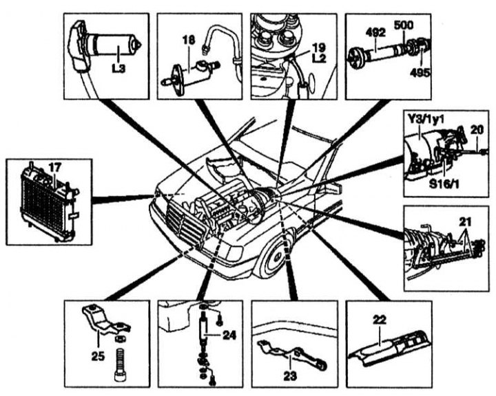
17 - Gearbox radiator; 18 - Clutch position sensor; 19 - Speedometer shaft; 20 - Gearshift lever; 21 - Gearshift rod; 22 - Heat shield; 23 - Bracket; 24 - Engine shock absorber; 25 - restrictive bracket of the engine; 492 - Cardan shaft; 495 - Intermediate bearing of the cardan shaft; 500 - Nut; L2 - Inductive speed sensor; L3 - Speed sensor; S16 / 1 - Starter blocking switch; Y31/1y1 - AT
1. Disconnect the pipeline from the clutch position sensor (18).
2. Unscrew the speedometer shaft (19) and inductive speedometer sensor (L2).
3. Unscrew the speed sensor (L3).
4. Unscrew the bracket (23).
5. Detach the heat shield (22).
6. Unscrew the cardan shaft (492).
7. Disconnect the intermediate bearing (495) cardan shaft.
8. Loosen the nut (500) intermediate bearing.
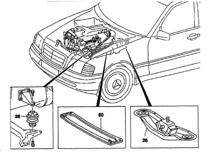
26 - Rear engine mount; 28 - Front engine mount; 50 - Crossbar

The design of the rear suspension support of the power unit (bottom view)
1 - Support; 2 - Crossbar; 3 - Engine bracket; 6 - Bolt M10x105; 7 - Bolt M8x15; 9 - Bolt M8x25; 10 - Bolt M10x25; 11 - Transmission
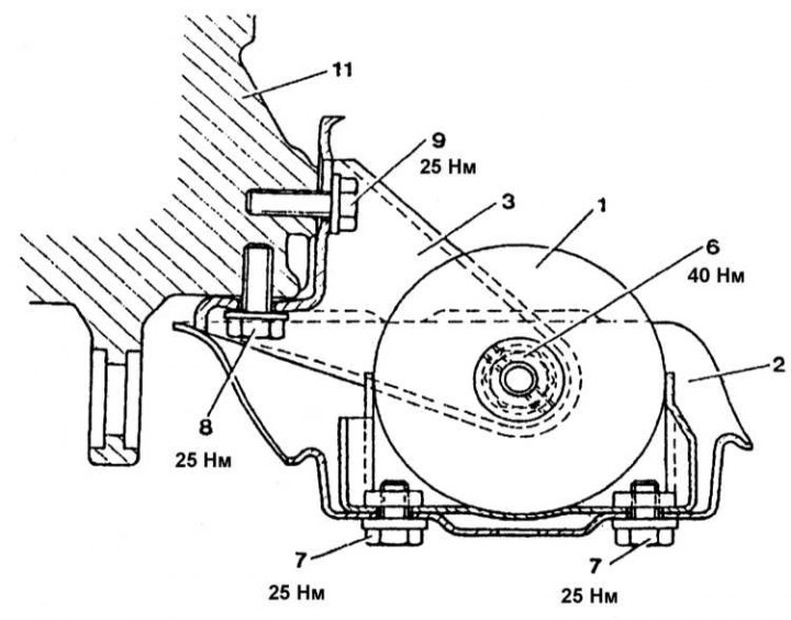
The design of the rear suspension support of the power unit (side view)
1 - Support; 2 - Crossbar; 3 - Bracket; 6 - Bolt M10x105; 7 - Bolt M8x15; 8 - Bolt M8x32; 9 - Bolt M8x25
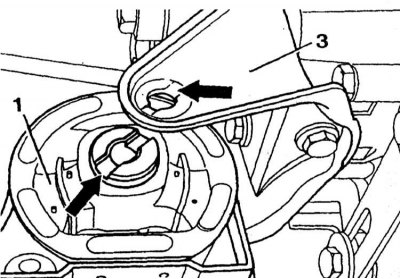
When installing the rear support, make sure it is correctly positioned
1. Unscrew the cross member (50).
2. Attach the lift to the engine.
3. Unscrew the rear engine support bracket (26). The design of the rear support is shown in Ref. illustrations.
4. Turn away bolts of fastening of forward support of the engine (28) from below.
5. Raise the engine using a hoist.
Installation
Installation is carried out in the reverse order of removal.