



Unscrew the brake caliper mount and hang it on a piece of wire next to the front suspension.
Remove the brake disc.
Remove the front wheel hub (section 13.2).
Unscrew the three mounting bolts and remove the brake disc protective cover.
Compress the suspension spring as described in section 13.2 and remove the spring from the lower wishbone.
Disconnect the ball joint of the steering rod from the steering arm or unscrew the bolts securing the steering arm to the steering knuckle and remove the arm.
Loosen the nuts securing the upper and lower ball joints and use a puller to disconnect the ball joints from the steering knuckle.
Remove the steering knuckle.
Check the condition of the ball joints and replace if necessary as described in section 13.7.
Installation must be carried out especially carefully so as not to disturb the suspension adjustment.
Place the upper and lower ball joints into the pivot pin holes and tighten the mounting nuts. Tighten the upper nut to 40 Nm and the lower nut to 80 Nm.
Compress the suspension spring, install it on the lower wishbone, check the position of the spring relative to the support surfaces. Remove the spring compression device.
Install the protective cover, screw in new mounting bolts and tighten them to a torque of 10 Nm.
Install the front wheel hub and adjust the axial clearance in the bearings as described previously.
Check the front wheel alignment and adjust if necessary (see section 13.9).
Adjust the headlights.
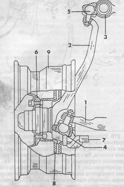
Fig. 218. Section of the steering knuckle and ball joints.
1 - lower wishbone,
2 - steering knuckle,
3 - upper transverse arm,
4 - lower ball joint,
5 - upper ball joint,
6 - front wheel hub,
7 - rotary lever,
8 - brake disc,
9 - wheel.
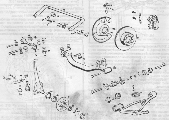
Fig. 219. Installing the front suspension.
1 - traverse,
2 - protective screen,
3 - lower wishbone,
4 - steering knuckle,
5 - upper transverse arm,
6 - lower ball joint,
7 - protective cover with locking rings,
8 - upper ball joint,
8a - protective cover with locking rings,
9 - front wheel hub,
9a - oil seal,
9v - tapered roller bearing internal,
9c - outer tapered roller bearing,
9d - split nut,
9th - cap,
9f - spring contact,
10 - anti-roll bar,
11 - front suspension spring disc support,
12 - radial torsion bearing of the front hinge of the lower transverse arm (2 execution),
13 - thrust bearing of the front hinge of the lower transverse arm (2 execution),
14 - Front rubber joint of the lower wishbone (1 execution),
15 - rear rubber joint of the lower wishbone,
16 - rubber joint of the upper wishbone,
17 - eccentric bolt with washer and nut of the front hinge,
18 - eccentric bolt with washer and rear hinge nut,
19 - rubber bushing of the front support of the anti-roll bar,
20 - bracket,
21a - clamp,
21 in - Allen key clamp bolt,
21c - bolts with washers and self-locking nuts,
21d - bushings,
21e - disc washers,
21f - rubber bushing,
21 g - bolt,
22 - rotary lever,
23 - brake caliper,
24 - brake disc,
25 - protective cover,
26 - brake hose holder.
(Information copied from the website: MERCEDESMAN)