
Cars BMW Cars Volkswagen Cars Chevrolet Cars Land Rover Cars Lada Cars Honda Cars Peugeot
English Русский
Български
Беларускі
Український
Српски
Hrvatski
Română
Polski
Slovenský
Magyar
Bookmark News and articles Sitemap Feedback Site search
MercedesMan.ru


A-Class C-Class E-Class G-Class M-Class S-Class Others
W116 (1972-1980, petrol) W126 (1979-1991, petrol) W140 (1991-1998) W220 (1998-2005)
  • Main
  • S-Class
  • W116 (1972-1980)
  • Chassis
  • Front suspension
  • Removal and installation the front suspension

Removal and installation the front suspension (Mercedes-Benz S-Class W116)

0
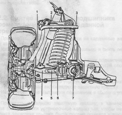
Fig. 210 shows half of the front suspension with the hub and wheel.

Fig. 210. Half of the front suspension.

Fig. 210. Half of the front suspension.
1 - steering knuckle,
2 - upper transverse arm,
3 - anti-roll bar,
4 - lower transverse arm,
5 - stretching,
6 - rubber hinge,
7 - stretch support.


Raise the front of the vehicle on stands as described in section 13.1 and remove the front wheels.

Loosen the union nuts of the brake system pipes and remove the spring clip from the hose holder. Plug the open end of the pipe.

Loosen the steering rod mount to the steering arm and disconnect the rod.

Place a stand under half of the pendant.

Unscrew the brake strut from the front part of the body base.

Mark the position of the eccentric bolt heads of the front and rear hinges of the lower wishbone relative to the crossmember or crossmember, unscrew the fastening nuts and remove the eccentric bolts from the hinges (Fig. 211).
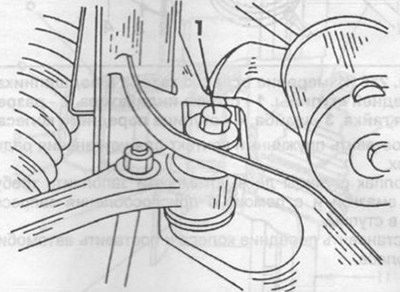
Fig. 211. Front eccentric bolt (wheel alignment).

Fig. 211. Front eccentric bolt (wheel alignment).
1 - eccentric bolt.


Remove the protective cover from the crossbar.


Remove the front and rear hinge components from the lower control arm.

Loosen the crossbar mounting bolts and lower the crossbar down (Fig. 212).
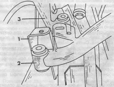
Fig. 212. Traverse.

Fig. 212. Traverse.
1 - longitudinal body reinforcement,
2 - traverse,
3 - lower transverse arm.


Disconnect the anti-roll bar from the upper wishbone.

Loosen the upper wishbone hinge mounting bolt and remove the bolt.

Remove half of the front suspension.

Check the condition of the wishbone joints and the rubber mounts of the anti-roll bar. Replace if necessary.

When installing half of the front suspension, perform the following work.

Place the front suspension half assembly on a jack and slowly lift it to the required installation position.

Secure the upper wishbone to the body and install the stabilizer bar mounting bolts. Do not tighten the mounting bolts completely. For the stabilizer bar to be positioned correctly, both halves of the front suspension must be at the same height.

Install the lower wishbone joint on the body crossmember. To do this, install the eccentric bolts in the joint according to the marks and tighten the nuts by hand. The eccentric bolts determine the installation of the wheels, so after assembly, it is necessary to check the installation of the wheels.


Install the crossmember on the longitudinal reinforcement of the body.

Install the brake strut to the front of the body base.

Install the brake system pipes. Turn the steering knuckles in both directions until they stop and check for harmful contact between the brake hoses and the front suspension components. If necessary, change the position of the hoses.

Install the front suspension spring (section 13.2).

Install the shock absorber (section 13.1).

Install the steering rod and tighten the mounting nut to 35 Nm. Hold the ball joint head with a hex key.

Bleed the brake system as described in section 17.7.

Place the car on its wheels, check again that the marks on the heads of the eccentric bolts and on the crossmember match (or on the traverse) and tighten the fastening nuts to a torque of 180 Nm. If there are no marks, set the eccentric bolts to the middle position.

Tighten the upper control arm hinge bolt and the stabilizer bar bolts.

Check the position of the car by the front suspension (section 13.6.4).

Check the front wheel alignment and adjust if necessary (section 13.6).

Check the headlight adjustment.
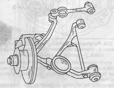
Fig. 213. Half of the front suspension.

Fig. 213. Half of the front suspension.
This article is available at: russian, bulgarian, belarusian, ukrainian, serbian, croatian, romanian, polish, slovak, hungarian
The article has been verified: Panova Maya Vladimirovna
Share with friends:
◀ Previous
S-Class W116 / Front suspension
Next ▶

Removal and installation the front suspension spring
Removal and installation the shock absorber
Adjusting the axial clearance of wheel hub bearings
Removal and installation the hub
Replacing bearings in the hub
Removal and installation the steering knuckle
Replacing ball joints
More similar articles for repairing other models

☛ Front suspension — device Mercedes W168 (1997-2004)
☛ Front suspension design Mercedes W202 (1993-2000)
☛ Design and technical characteristics of the front suspension Mercedes W123 (1976-1985)
☛ General information about the front suspension Mercedes W463 (1999-2019)
☛ Access to the right front seat storage compartment Mercedes W163 (1997-2005)
☛ Front and rear suspension — general information Mercedes Sprinter (1995-2000, diesel)
Link in different formats to this article
Comments and feedback from visitors
No comments yet


How much will 14 + 19 ?


W220 (1998-2005) 
  • General information
  • Introduction to guide
  • User manual
  • Maintenance
  • Power unit
  • Engine repair
  • Cooling and heating systems
  • Power and exhaust systems
  • Ignition and control system
  • Charge and launch systems
  • Transmission
  • Automatic gearbox
  • Drive shafts
  • Chassis
  • Brake system
  • Front suspension
  • Rear suspension
  • Steering
  • Body
  • Body elements
  • Electrical equipment
  • Equipment and devices
  • Electrical circuits
W140 (1991-1998) 
  • User manual
  • Controls and instruments
  • Driving and operation
  • Maintenance
  • Power unit
  • Petrol engine V6
  • Petrol engine V8
  • Petrol engine V12
  • Diesel engine OM603
  • Diesel engine OM606
  • Cooling system
  • Power supply and injection system
  • Control system HFM-SFI
  • Control system LH-SFI
  • Control systems ME-SFI
  • Diesel control system
  • Ignition system
  • Charge and launch system
  • Transmission
  • Mechanical gearbox 717.438
  • Mechanical gearbox 717.454
  • Automatic gearbox 722.5
  • Automatic gearbox 722.6
  • Clutch and drive shafts
  • Differential
  • Chassis
  • Brake system
  • Steering
  • Front suspension
  • Rear suspension
  • Body
  • Exterior (external elements)
  • Interior (internal elements)
  • Electrical equipment
  • Equipment and devices
  • Electrical circuits
W126 (1979-1991, petrol) 
  • Power unit
  • Engine repair
  • Ignition system
  • Lubrication system
  • Cooling system
  • Fuel system
  • Fuel injection system
  • Transmission
  • Clutch and cardan
  • Mechanical gearbox
  • Automatic gearbox
  • Chassis
  • Front suspension
  • Rear suspension
  • Steering
  • Brake system
  • Electrical equipment
  • Power devices
  • Electrical circuits
W116 (1972-1980, petrol) 
  • General information
  • Introduction to guide
  • Power unit
  • 8-cylinder V8 engine
  • 6-cylinder I6 engine
  • Cooling and lubrication system
  • Power system (carburetor)
  • Fuel injection system
  • Ignition system
  • Transmission
  • Clutch and cardan
  • Car gearbox
  • Chassis
  • Front suspension
  • Rear suspension
  • Steering
  • Brake system
  • Electrical equipment
  • Power devices
  • Electrical circuits
 
MercedesMan.ru © 2017–2026 · Mobile version · Read about Mercedes · Sitemap: EN BG BY UA RS HR RO PL SK HU · Feedback · Site search · Bookmark A-Class (W168) · C-Class (W201) · C-Class (W202) · C-Class (W203) · E-Class (W123) · E-Class (W124) · E-Class (W210) · G-Class (W463) · M-Class (W163) · S-Class (W116, petrol) · S-Class (W126, petrol) · S-Class (W140) · S-Class (W220) · Sprinter · Vito 1 · Vito 2 · Vario 814D ·
 
We only use cookies without which some of the site's features may not be available.