
The amount of air supplied is constantly measured by the air flow meter, and the amount of fuel injected is strictly proportional to the amount of air supplied (except for certain engine operating conditions such as cold start, full load operation, etc.) and regulated by a fuel dispenser.
Schematic diagram of the fuel injection system «K-Jetronic»
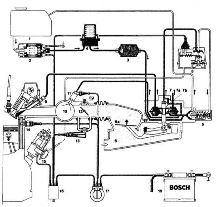
1 - fuel tank; 2 - fuel pump; 3 - fuel filter; 4 - fuel accumulator; 5 - supply pressure regulator; 6 - air flow meter; 7 - dispenser-distributor of fuel; 8 - control pressure regulator; 9 - injection nozzle; 10 - intake manifold; 11 - starting nozzle; 12 - throttle valve; 13 - valve for additional air supply; 14 - temperature sensor; 15 - distributor; 16 - relay block; 17 - ignition switch; 18 - battery