



Contents: Pressure regulator ↡ Distribution plunger ↡ Differential pressure valves ↡ Control pressure circuit ↡ Control pressure regulator ↡ Additional air supply valves ↡
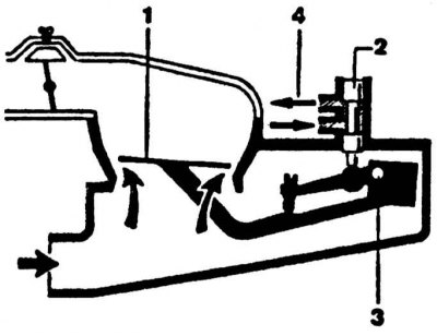
Operating principle of the fuel quantity meter
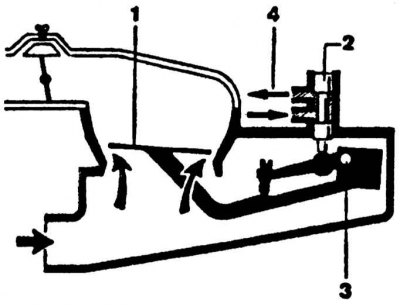
1 - pressure disc; 2 - distribution plunger; 3 - lever axis; 4 - to the intake valves
Operating principle of the fuel dispenser-distributor
1 - valve spring; 2 - diaphragm; 3 - distribution plunger; 4 - slotted sleeve of the distribution plunger; 5 - lower chamber; 6 - upper chamber; 7 - fuel supply to the injectors; 8 - control edge of the distribution plunger
The metering distributor regulates the amount of fuel supplied to the injectors in proportion to the amount of air supplied.
The fuel metering distributor consists of a pressure regulator, a distribution plunger, differential pressure valves and a control pressure circuit.
Pressure regulator
The pressure regulator regulates the fuel supply pressure within the range of 4.5-5.2 kg/cm². Excess fuel returns to the tank through the drain pipe.
When the engine is stopped, the pressure regulator reduces the fuel pressure in the system to a value slightly lower than 3.3 kg/cm², i.e. the opening pressure of the injectors. This eliminates the possibility of spontaneous combustion of the working mixture.
Distribution plunger
The amount of fuel supplied to the engine cylinders changes depending on the position of the distribution plunger, in the walls of which there are rectangular slots, the flow section of which changes as the plunger moves relative to the windows (one window per cylinder), made in the plunger sleeve.
Fuel dosed in this way (proportional to air flow) is supplied to the upper chambers of the differential pressure valves.
Differential pressure valves
Four differential pressure valves (one per cylinder) have two chambers separated by a diaphragm. Regardless of the amount of fuel supplied, they maintain a constant pressure drop at the level of the distribution plunger slots, due to which the fuel pressure in the system and the pressure of the fuel supplied to the injectors are maintained at a constant level.
As the fuel supply to the upper chambers increases, the pressure increases, the diaphragm bends downward, completely opening the fuel supply holes to the injectors.
When the fuel supply to the upper chambers decreases, the diaphragm bends upward, reducing the flow area of the fuel supply holes to the injectors.
Control pressure circuit
The pressure in the control circuit is regulated by a pressure regulator and can vary within the range from 0.5 kg/cm² on a cold engine to 3.4-3.8 kg/cm² on a warm engine. With the throttle valve fully open, the control pressure decreases to 2.9 kg/cm², causing enrichment of the working mixture at full engine load.
To prevent uncontrolled beating of the air flow meter pressure disk under the influence of air flow pulsations (at low crankshaft speed or at full engine load) a shock-absorbing throttle constriction is provided.
Control pressure regulator
The control pressure regulator ensures enrichment of the working mixture entering the combustion chambers during engine warm-up. On a cold engine, the bimetallic spring compresses the diaphragm valve spring, opening the fuel drain channel, which reduces the counteraction on the distribution plunger. A decrease in the control pressure with constant air flow causes an increase in the stroke of the pressure disk. As a result, the distribution plunger is additionally lifted, increasing the amount of fuel supplied to the injectors.
As the bimetallic spring heats up, the pressure on the spring of the diaphragm valve of the control pressure regulator decreases and the drain channel slowly closes. The control pressure reaches the normal value and enrichment of the combustible mixture stops.
The control pressure regulator is installed on the cylinder block, due to which its temperature changes simultaneously with the engine temperature. This eliminates excessive enrichment of the working mixture at an average temperature.
Operating principle of the control pressure regulator
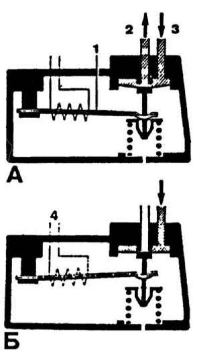
A - on a cold engine; B - on a hot engine; 1 - bimetallic spring; 2 - drain fuel; 3 - control pressure supply; 4 - thermal winding of bimetallic spring
Additional air supply valves
This valve serves to increase the crankshaft speed during engine warm-up. When starting a cold engine, the additional air supply channel is opened by the rotary valve flap, which moves when the bimetallic spring heats up. As the engine warms up, the additional air supply channel gradually closes.
(Material based on data from the portal: «mercedesman»)
In addition, the supply of additional air is regulated by the pressure disk of the air quantity meter, the movement of which leads to a corresponding rise of the distribution plunger, which also contributes to an increase in the crankshaft speed (with the throttle valve closed).
When starting a cold engine, the electromagnetic starting injector, controlled by a thermal time relay, sprays an additional amount of fuel into the intake manifold.
Fuel is supplied to the starting injector directly from the distributor under a pressure of approximately 4.7 kg/cm².
The maximum operating time of the injector at a temperature of minus 20°C is 8 s. At a coolant temperature above 15°C, the starting injector does not turn on.