
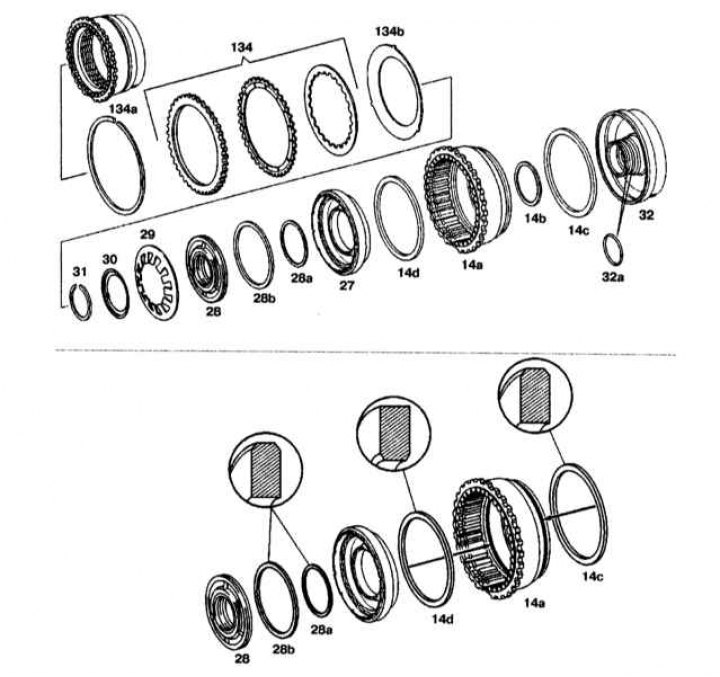
14a - External brake support B2 or piston B3; 14b-d - O-rings for brake B3; 27 - Brake piston B2; 28 - Piston guide ring; 28a-b - O-rings on the piston guide ring; 29, 134b - Disc springs; 30 - Spring plate; 31, 134a - Retaining rings; 32 - Brake piston guide B2 and B3; 32a - O-ring; 134 - Disc block
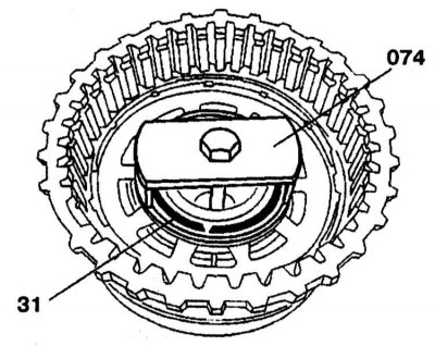
31 - Retaining ring; 074 - Puller
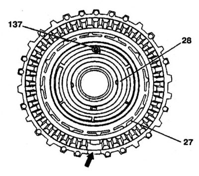
27 - Piston; 28 - Piston guide ring; 137 - Valve
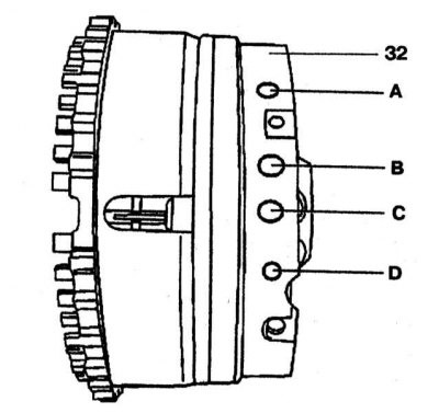
A - Oil channel of piston B3; B - Oil channel of piston B2 on the reverse side; C - K3 clutch oil channel; D - Piston oil channel B2 on the shift side
Assembling the Piston Guide and Outer Bearing of the B2 Multi-Disc Brake
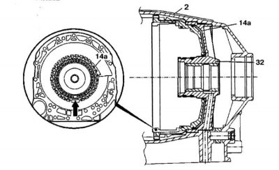
2 - Transmission housing; 14a - Outer brake support B2, (piston B3); 32 - Piston guide
Cross section of brake B1
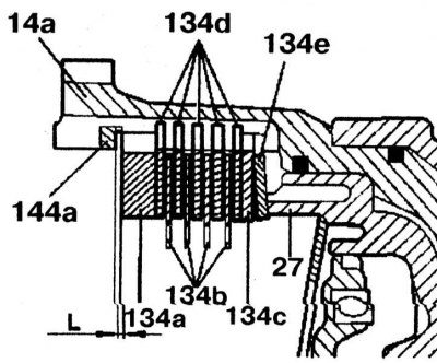
14a - External brake support B2; 27 - Piston B2; 134a - Outer disk (6.5 mm thick); 134b - Outer disk (1.8 mm thick); 134s - Outer disk (1.8 mm thick); 134d - Friction discs; 134e - Disc spring; 144a - Retaining ring; L - Clearance
Disassembly
1. Remove retaining ring (134a).
Options | ||
| Clearance in the multi-disc brake B1, mm | Disc 2 | 1,90-2,30 |
Disc 3 | 2,00-2,40 | |
Disc 4 | 3,00-3,40 | |
2. Remove the brake disc block B2 (134) and disc spring (134b) from the outer brake support B2.
3. Install the puller (074) on disc spring (29) and squeeze it until the groove for the retaining ring is released.
4. Remove retaining ring (31).
5. Remove the spring plate (30) and disc spring (29).
6. Detach the guide ring (28) piston and brake piston B2 (27) from piston B3 (14a), supplying compressed air to hole D (refer to accompanying illustration).
7. Press the guide ring (28) from piston B2 (27).
8. Remove the guide (32) from piston B3 (14a), by supplying compressed air to port A.
Assembly
1. Install the guide (32) and piston B3 (14a) to the correct position. To do this, insert a guide (32) into the transmission housing (2) and tighten. Press in outer brake mount B2 (14a) all the way to the guide (32). Groove on the splines or cutout on the outer support of the brake B2 (14a) should be pointing down (arrow).
2. Insert brake piston B2 (27) into brake piston B3 (14a). Rounded O-Ring Ends (14s), (28a) And (28b) must face outward Rounded end of the O-ring (14d) must be directed inward (refer to accompanying illustration 17.1).
3. Insert guide ring (28) piston. Valve (137) in the guide ring, the piston must be on top.
4. Insert disc spring (29) and spring plate (30).
5. Install the puller (074) on disc spring (29) and squeeze it until the groove for the retaining ring is released.
6. Insert retaining ring (31).
7. Insert disc spring (134b) and disk block (134) on the outer brake support B2.
8. Install B3 brake discs together in the order shown in the illustration (109) and insert them one by one.
9. Install the press (078) to an external drive (70s).
10. Compress the disc stack with a press until it stops until the marking ring is visible (small arrow).
11. Measure the gap L at three points between the circlip (144a) and outer disc (134a). The size of the gaps in the multi-disc brake (AT 2) are given in the table.
Options | ||
| Clearance in the multi-disc brake B2, mm | Disc 4 | 1.90-2.30 |
Disc 5 | 2.00-2.40 | |
12. Adjust the gap with the retaining ring (144a), if it is needed. Retaining ring thickness: 2.9, 3.2, 3.5, 3.8 and 4.1 mm.
13. Install retaining ring (134a).