
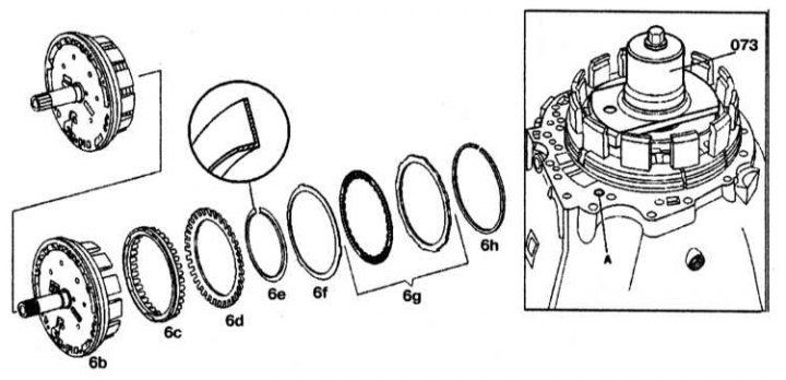
6b - Outer brake support B1; 6s - Piston; 6d - Piston return disc spring; 6f - Disc spring of the disc block; 6g - Block of gears; 6e, 6h - Retaining rings; 073 - Puller; A - Brake oil channel B1
Cross section of brake B1

6b - Outer brake support B1; 6s - Piston; 6f - Disc spring; 6h - Retaining ring; 69 - Friction discs; 70a - Outer disk 1.8 mm thick; 70b - 3.5mm outer disc/new 2.8mm disc; 70s - Outer disk 4.0 mm thick; «L» - Clearance
Disassembly
1. Remove retaining ring 6h.
2. Remove disc pack 6g and disc spring 6f from outer support.
3. Install puller 073 on disc spring 6d and compress it until the circlip groove is free.
4. Remove the circlip 6e.
5. Remove the piston 6c from the outer support by carefully blowing air into port A.
Assembly
1. Install the piston 6c on the outer support.
2. Install disc spring 6d
3. Install puller 073 on disc spring 6d and compress it until circlip 6e is seated in the groove.
4. Insert retaining ring 6e.
5. Insert disc spring 6f and disc assembly 6g on the outer support and measure clearance L. Insert brake discs B1 together in the order shown in the illustration and install them one by one.
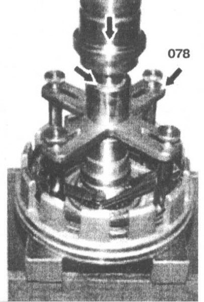
6. Install press 078 on outer disc 70c.
7. Squeeze the disc stack until it stops (until the marking ring is visible) (small arrow).
8. Measure clearance «L» between retaining ring 6h and outer disc 70c at three points. The gaps in the multi-disc brake B1 are shown in the table.
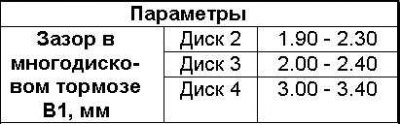
9. Adjust the clearance with the circlip 6h if necessary.
Retaining ring thickness: 2.6, 2.9, 3.2, 3.5, 3.8 and 4.1 mm.
10. Install retaining ring 6h.