
Cooling circuit diagram
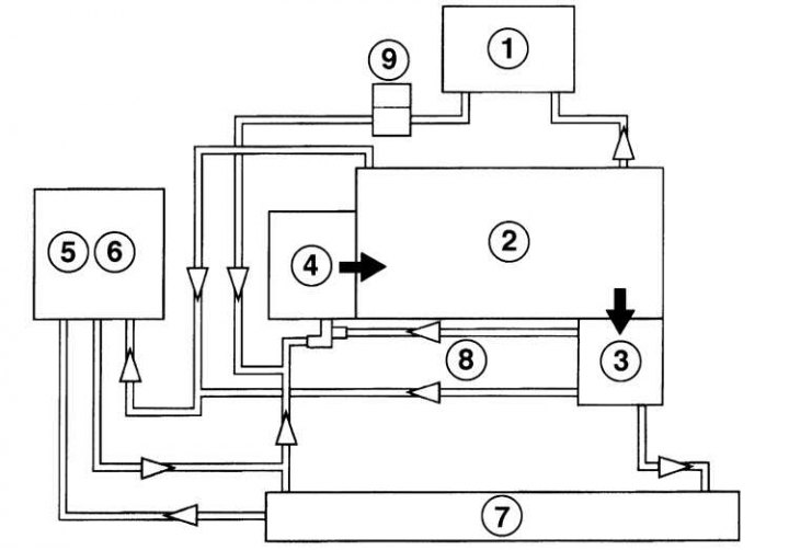
1 - Heater; 2 - Engine; 3 - Thermostat; 4 - Water pump; 5 - Expansion tank; 6 - Cover with valve; 7 - Radiator; 8 - Bypass hose; 9 - Oil cooler
Radiator and fan
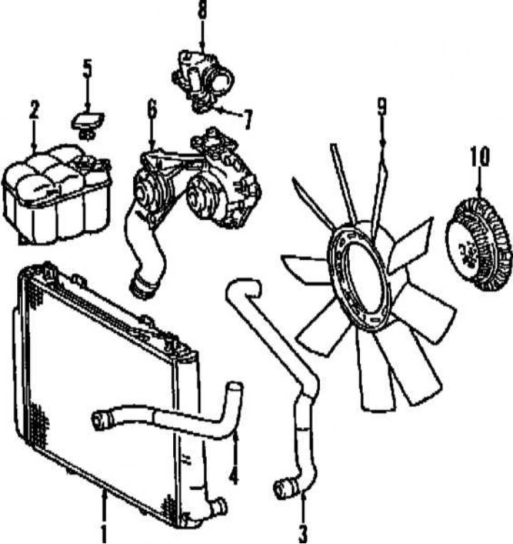
1 - Radiator; 2 - Expansion tank; 3 - Upper radiator hose; 4 - Lower radiator hose; 5 - Expansion tank cover; 6 - Water pump; 8 - Thermostat; 9 - Fan impeller; 10 - Vibration damper
While the engine is not warmed up, the coolant circulates only in the head and cylinder block and in the passenger compartment heater heat exchanger. As the coolant temperature rises, the thermostat opens the large cooling circuit. The coolant is directed through the radiator by a constantly running pump. The liquid passes through the radiator from top to bottom and is cooled by the air passing through it.
Heating and ventilation system
The heating system consists of fans and heat exchangers located in the blocks of the front and rear parts of the cabin. The hot coolant flows through the heat exchangers. When the heater mode control knob located on the control panel is moved, the valves open and hot air begins to flow into the vehicle interior. If you turn on the heater fan, air will be forced into the passenger compartment.
Intake air passes through a filter before entering the passenger compartment (contact the head Current service). The bulk of the dust particles will settle in the filter. The filter replacement interval must be observed. A filter blocked by dust will restrict the air supply to the passenger compartment, resulting in air stagnation inside the passenger compartment.
The distribution of air flows of the ventilation system is carried out with the help of dampers. The mode of air circulation is provided. The flaps are controlled by servo drives.