
Functional diagram of the HF circuit
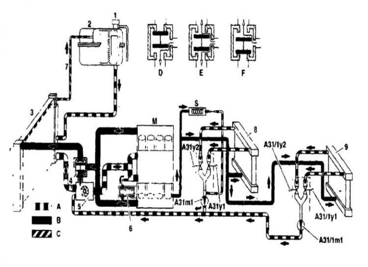
1 - End cap; 2 - Expansion tank; 3 - Radiator; 4 - Thermostat; 5 - Water pump; 6 - Oil filter equipped with a heat exchanger; 7 - Ventilation line; 8 - Heat exchanger of the heater; A - Coolant return; B - Coolant supply; C - Ventilation line; D - Short circuit mode; E - Combined mode; F - Fan mode; M - Motor; S - Windshield washer fluid reservoir; A31m1 - Water pump; A31y1 - Left double valve; A31y2 - Right double valve. On models with rear air conditioning (code 528); 9 - Heat exchanger of the heater; A31 1m1 - Water pump; A31 1y1 - Left dual valve; A31 1y2 - Right double valve
Temperature Control
The captions also refer to the figures below.
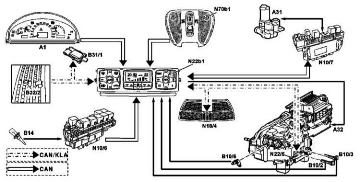
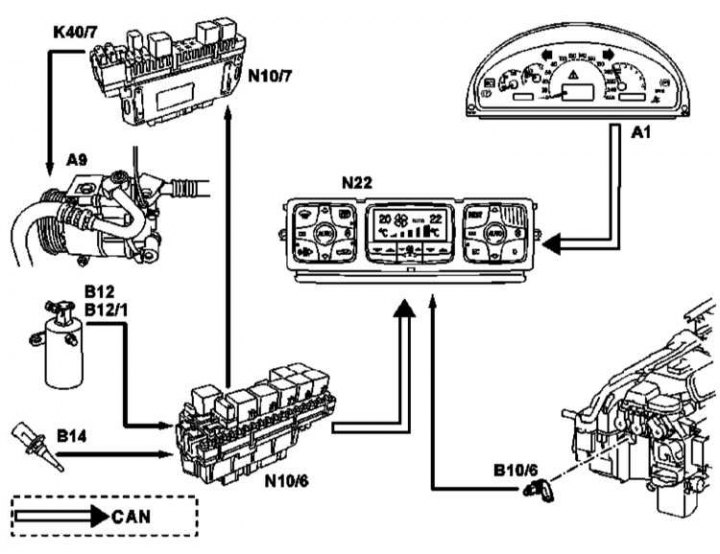
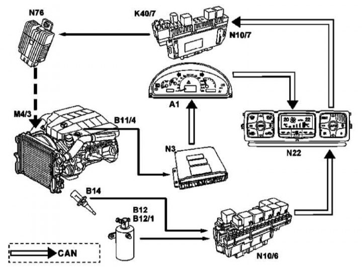
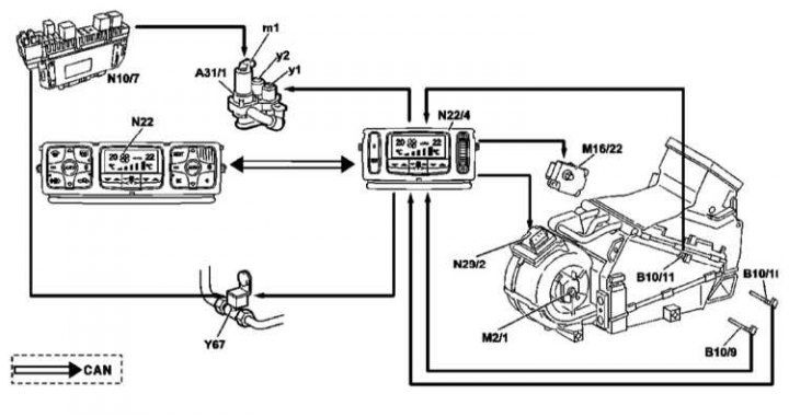
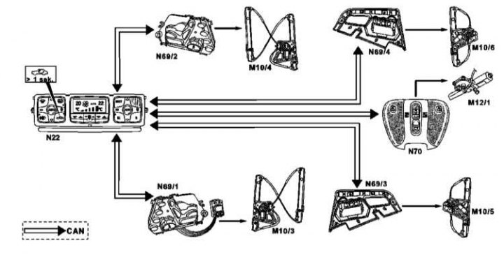
A1 - Dashboard; A9 - A/C compressor; A31 - Heating system delivery unit (including coolant circulation pump and right and left double valves); A31/1 - Power supply unit for rear reinforced heater; A31/1m1 - Coolant circulation pump; A31/1y1 - Left double valve; A31/1y2 - Right double valve; A32 - Heating system circulation unit; B10/2 - Left heater temperature sensor; B10/3 - Right heater temperature sensor; B10/6 - Evaporator temperature sensor; B10 / 09 - Temperature sensor for the left heater of the rear K / V; B10 / 10 - Temperature sensor of the right rear K / V heater; B10 / 11 - Rear A/C evaporator temperature sensor; B11 / 4 - Coolant temperature sensor; B12 - Refrigerant pressure sensor; B12/1 - Refrigerant temperature sensor; B14 - Outdoor temperature sensor; B32/2 - Additional air control sensor (AAC); K40/7 - Front right relay and fuse box; M2/1 - Rear purge motor; M4/3 - Exhaust fan (engine/AAC); M16/22 - Drive motor for the distribution of ascending and descending air flows; N3 - Control unit for constant fuel injection (CFI); N10/6 - Front left SAM; N10/7 - Front right SAM; N22 - AAC off button control unit; N22 / b1 - Cabin temperature sensor in the control unit of the AAC off button; N22/4 - Rear A/C control unit; N22/5 - Electronic stepper motor control unit; N29 / 2 - Regulator purge rear K / V; N70/b1 - Cabin temperature sensor in the upper console control unit; N76 - Engine fan control unit and K / V; Y67 - Refrigerant shut-off valve, rear A/C; M10/3 - Left front power window drive motor; M10/4 - Right front power window drive motor; M10/5 - Left rear power window drive motor; M10/6 - Right rear power window drive motor; M12/1 - Top hatch drive; N69/1 - Left front door control unit; N69/2 - Right front door control unit; N69/3 - Left rear door control unit; N69/4 - Right rear door control unit; N70 - Upper console control unit
KV refrigerator compressor control (the decoding of the symbols is given above)
Cooling fan control / HF (the decoding of the symbols is given above)
Temperature control (the decoding of the symbols is given above)
Convenience system interlock control (the decoding of the symbols is given above)
The air conditioning system consists of a condenser located in front of the radiator of the cooling system, an evaporator located next to the heat exchanger of the heater, a compressor driven by a drive belt, a receiver / dryer, as well as various pipes connecting the components listed above. A damper is installed at the inlet of the evaporator, which provides the pressure drop necessary for the operation of the system.
The fan delivers warm air from the passenger compartment to the evaporator (analog radiator), where heat from the air is transferred to the refrigerant. The refrigerant then evaporates and leaves the evaporator.
Diagrams of devices and components interconnected with HF are shown in the illustrations.
Attention! The system is under pressure. Do not attempt to disconnect any pipes related to the air conditioning system without first removing the working fluid from it. Removing fluid from the system is a rather complicated operation that must be performed at a service station. The system contains refrigerant type R134a. Make sure the station has the equipment required for this type of refrigerant. Wear safety goggles when disconnecting the system tubing.
If your vehicle has an air conditioning system, observe the following precautions when servicing any of its components:
- a) The R134a refrigerant currently in use is significantly less corrosive than the former R12 refrigerant. However, it is very hazardous to health. Avoid contact with eyes or skin - you may get burned. Although not toxic, its fumes can cause suffocation - do not remove it from the system while in an enclosed area. Its vapors are heavier than air, so do not stand under the vehicle when removing it from the system.
- b) Keep refrigerant vapors away from open flames. When it burns, poisonous gas is released. Gas mixed with air in a certain proportion can become explosive. Inhaling vapors through a lit cigarette can lead to tragic consequences.
- c) Do not allow refrigerant to enter the atmosphere. Unlike R12, refrigerant type R134a does not cause ozone depletion, but leads to a greenhouse effect in the atmosphere.
- d) The system uses seals made of a special material designed to work with a given type of refrigerant (for R134a - green). In order not to accidentally mix different types of refrigerants, certain types of adapters are used to charge a specific type of refrigerant.
- e) The system should be discharged at a Daimler-Benz workshop.
- f) Before carrying out any work related to the heating of any vehicle components (welding, soldering, drying after painting), discharge the system. It is also necessary to discharge the system before servicing any of the air conditioning system components.