
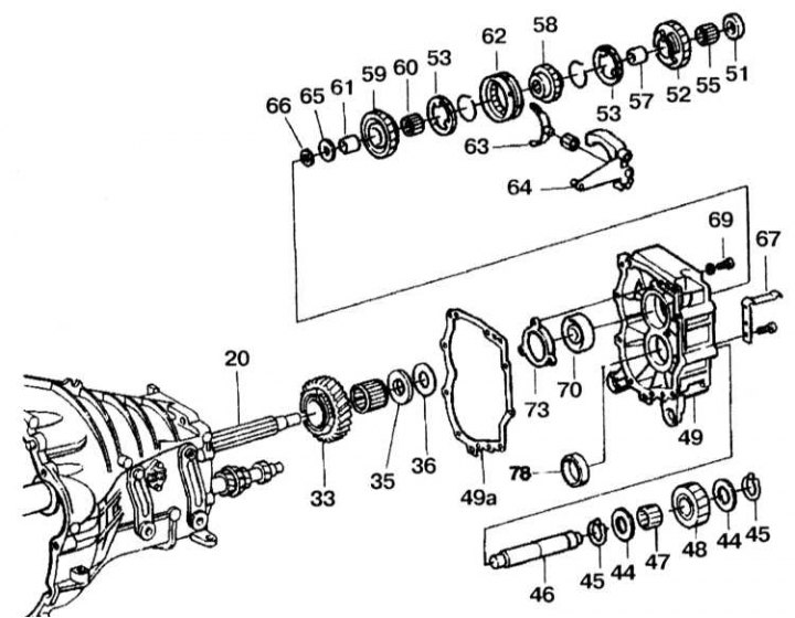
Details of installation of an intermediate crankcase
20 - Driven shaft; 33 - Helical gear of the 2nd turn over; 35, 65, 73, 78 - Outer races of bearings; 36, 44, 49a, 66 - Gaskets; 45 - Retaining ring; 46 - Reverse gear shaft; 47, 55, 60 - Needle bearings; 48 - Reverse gear; 49 - Intermediate plate; 51 - Hub; 52 - Helical reverse gear; 53 - Synchronizer ring; 57, 61 - Bushings; 58 - Synchronizer; 59 - Helical gear 1st gear; 62 - 1st gear clutch; 63 - Fork inclusion; 64 - Lever on; 65 - Friction ring; 67 - Leaf spring; 69 - Bolt; 70 - Ball bearing
Removing
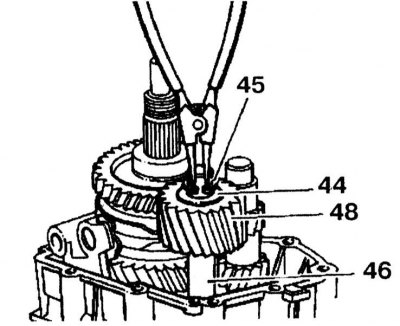
1. Remove retaining ring (45). Remove reverse gear (48) with needle bearing and two seals (44) reverse shaft (46).
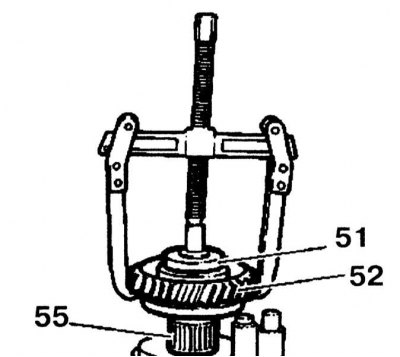
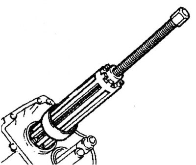
2. Remove the helical gear (52) reverse gear with hub (51) using a puller and remove the needle bearing (55).
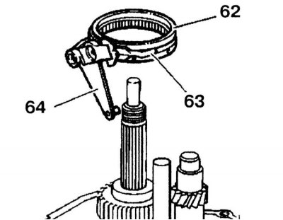
3. Remove the lever from the driven shaft (64), plug (63) and clutch (62) engaging 1st gear.
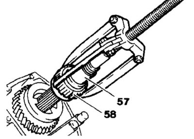
4. Remove the synchronizer (58) 1st/reverse gear with bushing (57) reverse gear.
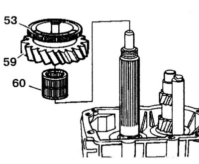
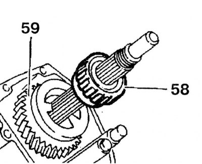
5. Remove the 1st gear helical gear from the driven shaft (59) with synchronizer ring (63) and needle bearing (60).
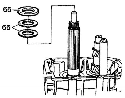
6. Using two screwdrivers, remove the friction ring (65) and sleeve (61) so that the friction ring (65) protruded by about 3 mm. If the sleeve is strongly pressed, it must be slightly heated.
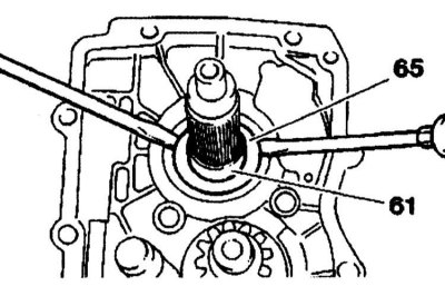
7. Remove the friction ring and bushing using a puller.
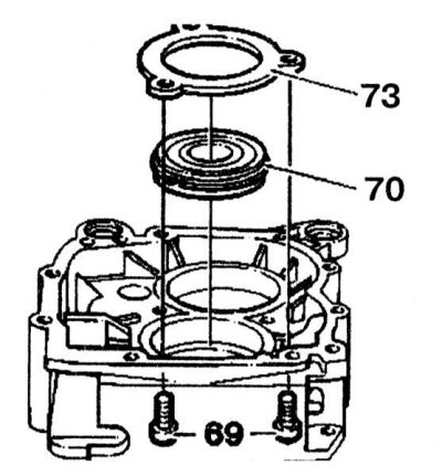
8. Remove the bolts (69) holder attachment.
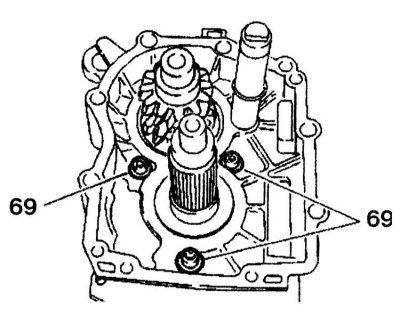
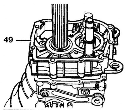
9. Remove intermediate housing (49) from the gearbox.
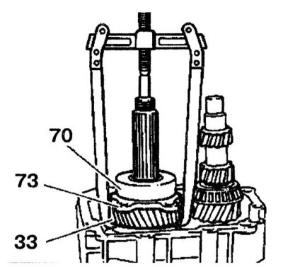
10. Using a puller, remove the 2nd gear helical gear (33) and ball bearing (70) with holder (73).
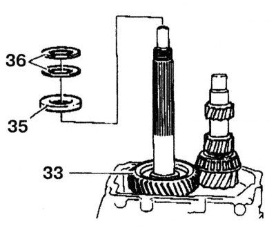
11. Remove the 2nd gear helical gear from the driven shaft (33) and gaskets (36).
Installation
1. Press in the ball bearing (70) into the intermediate plate and secure with the holder (73). Tighten the bolts (69) with a force of 30 Nm.
2. Replace gasket.
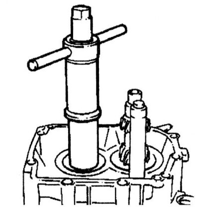
3. Using a press, press the intermediate plate onto the driven shaft and gearbox housing.
4. Install gaskets (66) on the friction ring (65).
5. Install the synchronizer (58) flange towards the bevel gear (59) 1st gear. Heat up the sleeve to approximately 80°C.
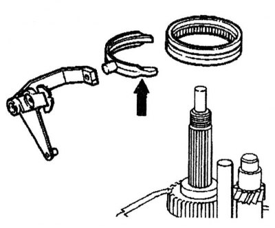
6. Insert the fork into the lever so that the short arm (arrow) located towards the reverse clutch.
Further installation is carried out in the reverse order of removal.