
Models with mechanical type VSS
Installation Details of Mechanical Type VSS
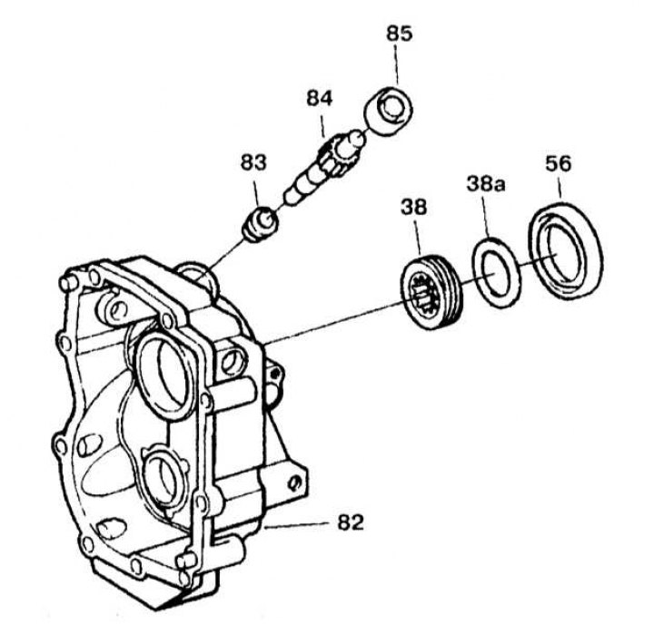
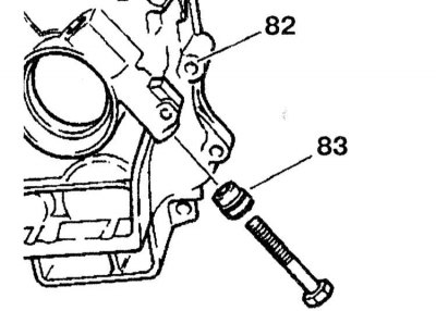
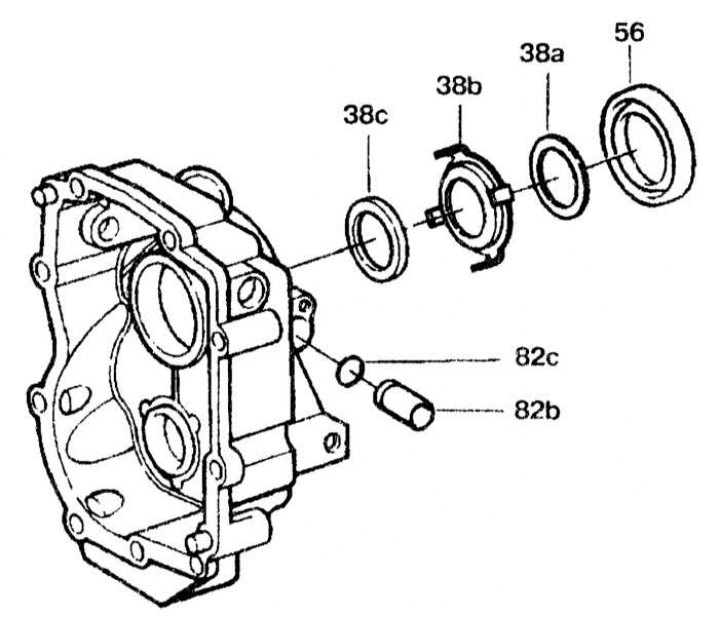
38 - Helical speedometer drive gear; 38a - Gasket; 56, 83 - Oil seals; 84 - Speedometer drive gear; 85 - Lid
Removing
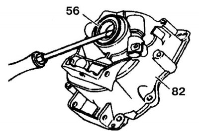
1. Remove the oil seal (56) from the rear cover of the gearbox (82).
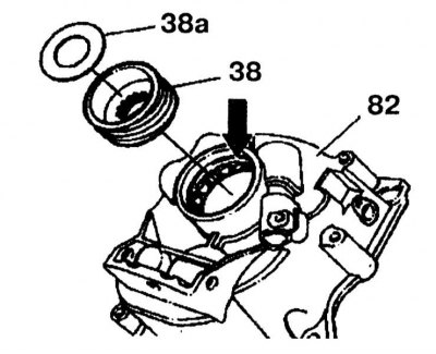
2. Remove the speedometer drive helical gear (38) and gasket (38a) from the rear cover of the gearbox (82).
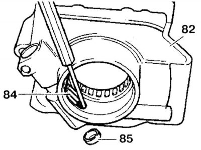
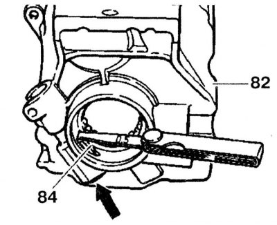
3. Remove the cover (85) using a punch. Remove the speedometer gear (84) from the rear cover of the gearbox (82).
4. Remove the radial oil seal (83) from the rear cover of the gearbox (82). To facilitate its removal, screw an M12 bolt into the radial oil seal and secure the head of the bolt in a vise.
Installation
1. Press in the stuffing box until it stops.
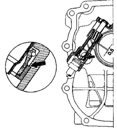
2. Install the speedometer gear (84) in the rear cover of the gearbox (82). Install cover (arrow) using a punch so that the gap between the gear and the rear cover of the gearbox is 0.5 mm.
3. Insert the speedometer drive helical gear (38) chamfered towards the roller bush (arrow) and press the gasket (38a) in the rear cover of the gearbox (62).
4. Further installation is carried out in the reverse order of removal.
Models with electronic VSS
Electronic VSS Installation Details
38a - Gasket; 38b - Rotor; 38c - Sleeve; 56 - Oil seal; 62b - Inductive sensor; 82c - O-ring
Removing
1. Remove the radial oil seal (56) from the rear cover of the gearbox (82).

2. Remove the gasket (38a), rotor (38b) and sleeve (38c) from the rear cover of the gearbox (82).
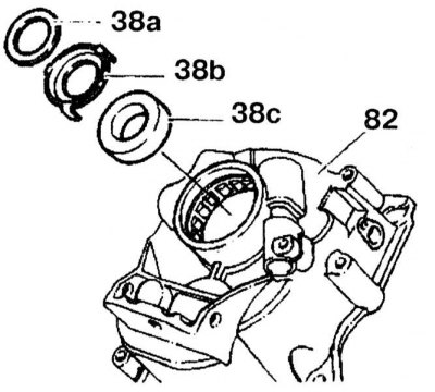
3. Use a drift to knock out the cover (02b) inductive sensor from the gearbox cover.

Installation
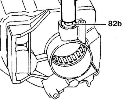
1. Carefully press the cover (82b) inductive sensor and a new O-ring into the gearbox cover using a punch.
2. Further installation is carried out in the reverse order of removal.