
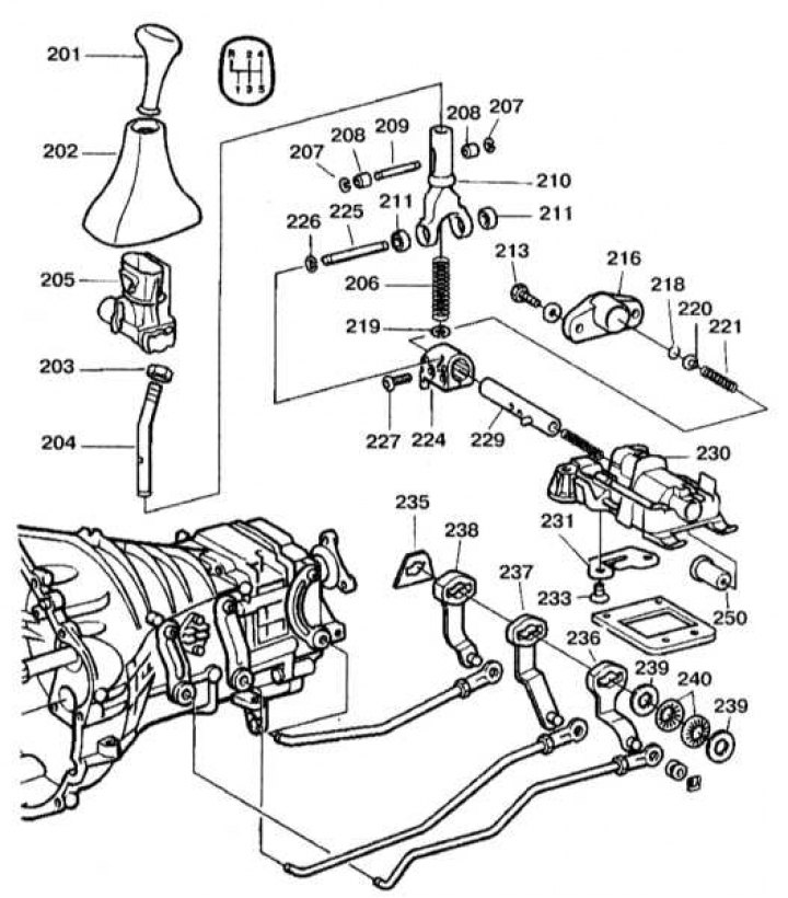
The design of the gear shift mechanism
201 - Decorative handle; 202 - Casing; 203 - Nut; 204 - Gear lever; 206, 221 - Springs; 204, 226 - Retaining rings; 218, 211 - Bushings; 209, 225, 279 - Fingers; 310 - Switch fork; 213, 227, 233 - Bolts; 216 - Bearing cap; 218, 220, 239, 240 - Gaskets; 224 - Locking eye; 230 - Bearing bracket; 231 - Locking plate; 230 - Plastic gasket; 236, 237, 238 - Intermediate shift levers
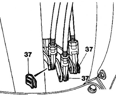
1. Set the shift lever to neutral, then disconnect the shift levers from the shift rods on the shift mechanism after removing the retaining clips (37).
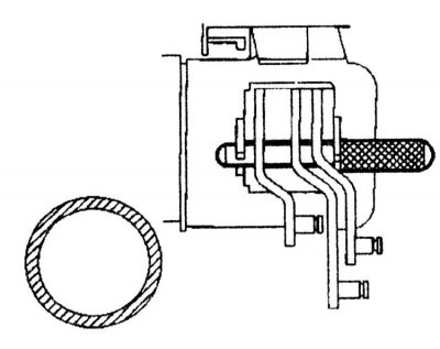
2. Position the three intermediate levers in the following sequence: reverse gear/1st gear, 2/3rd gear and 4/5th gear and block them with a lock pin through the holes.
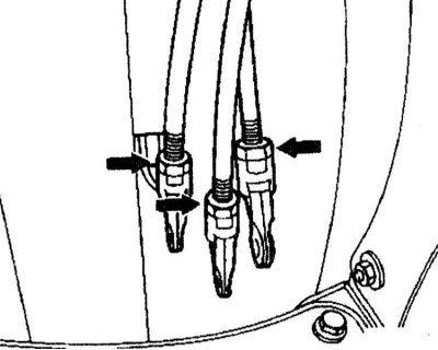
3. Loosen lock nuts (arrows) and adjust the length of each link.
4. Remove the lock pin from the intermediate shift levers.
5. Check up a gear change at the working engine.