
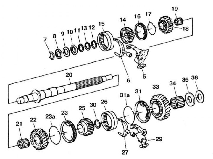
Intermediate shaft installation details
5 - 4th/5th gear lever; 6 - 4th/6th gear engagement fork; 7, 12, 13, 30 - Retaining rings; 8 - Axial bearing; 9, 35, 36 - Friction ring; 10 - Belleville spring; 11 - Gaskets; 14, 25 - Synchronizer; 15, 26 - Clutches of inclusion; 16, 23, 31 - Synchronizer rings; 17, 23a, 31a - Ring springs; 18 - Helical gear 4th gear; 19, 21, 34 - Needle bearings; 20 - Intermediate shaft; 22 - Helical gear 3rd gear; 27 - 2nd/3rd gear engagement fork; 29 - 2nd / 3rd gear lever; 33 - Helical gear 2nd gear
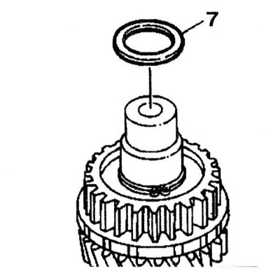
Disassembly
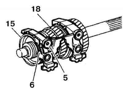
1. Turn the lever (5) 4/5th gears by 90°and remove it together with the fork (6) and clutch (15).
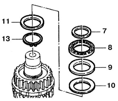
2. Using a screwdriver, remove the retaining ring (7). Remove the axle bearing (8), friction ring (9), belleville spring (10), gasket (11) and retaining ring (13) from the driven shaft.
3. Reinstall retaining ring (7).
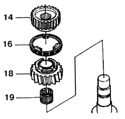
4. Remove the circlip from the driven shaft (12) synchronizer (14).
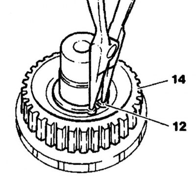
5. Remove the synchronizer from the driven shaft (14), helical gear 4th gear (18) with ring (16) and needle bearing (19).

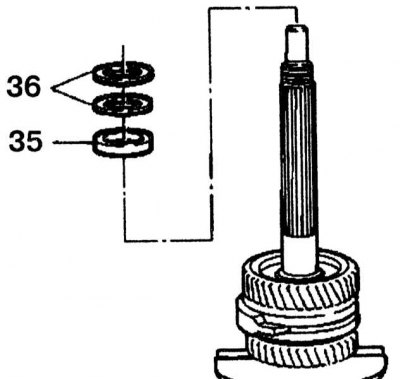
6. Remove the gaskets from the driven shaft (36) and friction ring (35).
7. Remove the 2nd gear helical gear from the shaft (33) with synchronizer ring (31) and needle bearing (34).
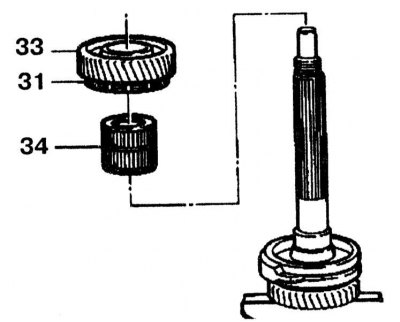
8. Remove the synchronizer ring from the 2nd gear helical gear.
9. Remove the lever of inclusion of 2/3rd transfers with a fork and the coupling. Rotate the lever 90°and remove the fork.
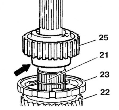
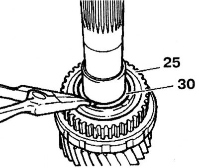
10. Remove retaining ring (30) 2/3 gear synchronizer (25).

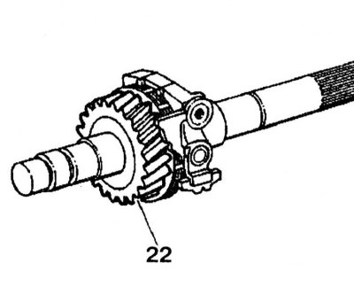
11. Remove the synchronizer (25) 2/3rd gear and 3rd gear helical gear (22 with ring (23) and needle bearing (21) from the driven shaft.
12. Remove the synchronizer ring (23) with helical gear 3rd gear (22).
Assembly
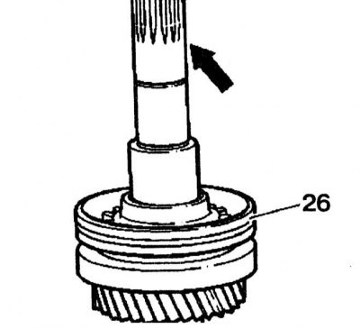
1. Install the synchronizer (25) on the driven shaft with the edge towards the 3rd gear helical gear (22) (arrow).

2. Make sure the retaining ring is (30) correctly installed in the groove.
3. Install the 2/3rd clutch (26) on the driven shaft so that (2) the grooves were directed towards the splines.
4. The locking element of the shift lever must be installed towards the 3rd helical gear (22).
5. Press the 4th synchro ring onto the helical gear until the annular spring is seated in the groove.
Further installation is carried out in the reverse order of removal.