
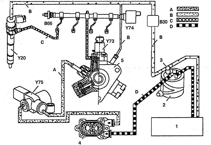
Pic. 5.52. Functional diagram of direct fuel injection
CDI: 1. Fuel tank,
2. Fuel filter,
3. Fuel heating valve,
4. Fuel pump,
5. High pressure fuel pump,
B30. fuel temperature sensor,
B66. Fuel pressure sensor in the distributor,
Y20. Nozzle,
Y73. High pressure fuel pump shut-off valve,
Y74. Fuel pressure control valve in the distributor,
Y75. Fuel cut-off valve.
A. Low fuel pressure,
B. Draining fuel,
C. High fuel pressure,
D. Fuel intake.
Part of the fuel flow passes through the high pressure fuel pump restrictor and through the pressure control valve in the Y74 distributor. Further, the flow through the fuel temperature sensor VZO passes into the heating valve 3. Then the fuel through the fuel filter 2 enters either again into the fuel pump 4 or into the fuel tank 1.
Another part of the fuel fills the pressure chamber of the high pressure fuel pump 5. From there, the fuel in compressed form (up to 1350 bar) fed into the distributor. The fuel pressure sensor in the B66 distributor is located in the distributor to determine the operating pressure. The pressure control valve in the Y74 distributor controls the pressure of the fuel flow, and if it is greater, some of the fuel is directed to the return fuel line. The fuel flow from the distributor is fed to the Y20-Y23 solenoid injectors, which are controlled directly by the engine control unit. Fuel that has not been injected into the cylinders, along with fuel leaks through the needle valve and control plunger, drains into fuel tank 1.