



Contents: Removal ↡ Installation ↡
Removal
1. Reduce the pressure in the air lines by loosening tube 6 on pneumatic chamber 2 (figure 5.36).
2. Unscrew the air line 6 from the pneumatic chamber 2 from above.
3. Unscrew converter 11, disconnect tube 3 from pneumatic chamber 2.
4. Unscrew nut 10 and remove air chamber 2.
Installation
5. Installation is carried out in the reverse order of removal. Replace the sealing rings 9.
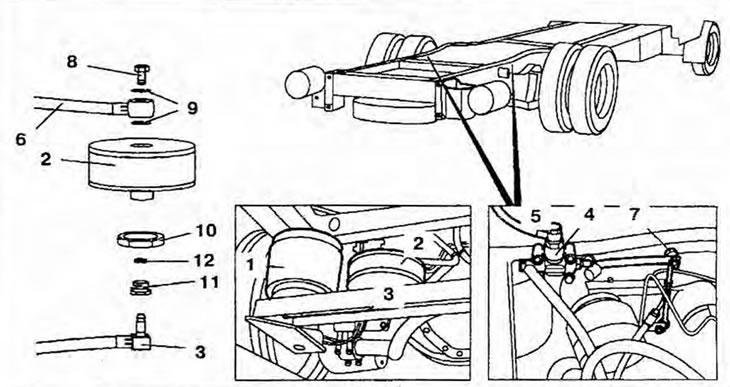
Figure 5.36. Rear axle air chamber (models 668, 670 with rear air suspension): 1 - Air support; 2 - Pneumatic chamber; 3, 5, 6 - Tubes; 4 - Rear axle height adjustment valve; 7 - Rear axle height adjustment valve drive rod; 8 - Bolt; 9 - Sealing rings; 10 - Nut; 11 - Converter; 12 - Expanding ring.