



Note: Individual characteristics are also given in the text of the Chapter and, if their implementation is mandatory, are highlighted in bold.
| General parameters (In brackets for models with extended base) Wheelbase, mm 2965 (3085) | Wheel track, mm | 1574 Minimum turning diameter, m | (In brackets for models with extended base) | Except 4MATIC | 11.7 (12.1) | 4MATIC | 11.8 (12.2) Front suspension | | Design Independent, 4-link, with pneumatic shock absorbers, adaptive damping system, automatically changing the rigidity of the shock absorber struts depending on the unevenness of the road, and ground clearance - depending on the speed. Anti-roll bar. Aluminum and steel elements are used | Rear suspension | | Design Independent multi-link, with pneumatic shock absorbers, adaptive damping system. Anti-roll bar. Aluminum and steel elements are used | Steering | | Design Rack and pinion, with hydraulic booster, speed-sensitive. Steering column - trauma-safe, telescopic, with a landing shift function and tilt adjustment | | Steering wheel turns | 2.8 from stop to stop | Power steering fluid | 1 l Wheel alignment angles | | Measuring suspension clearance corresponds to the angle of inclination of the drive shaft to the horizontal | Clearance | Measured in degrees, using the method shown in the illustration. 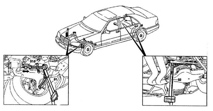 |
| 6.9° ±1.5° |
| -0.9° ±1° Front wheels | | Convergence | 0°32' ±10' (4.13±1.29 mm) | Wheel divergence at 20° turn | 1°37' ±30' Camber depending on the front suspension clearance (regulated) |
| -0°58' ±20' |
| -0°54' ±20' |
| -0°50' ±20' |
| -0°47' ±20' |
| -0°43' ±20' |
| -0°38' ±20' |
| -0°34' ±20' | The difference between the parties | 0°20' Longitudinal tilt of the wheel pivot axis depending on the ground clearance of the front and rear suspensions (regulated) 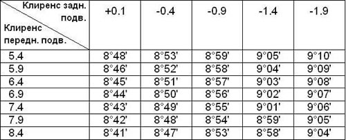 | The difference between the parties | 0°30' Rear wheels | Toe-in depending on rear suspension clearance (regulated) |
| 0°35' ±7' |
| 0°36' ±7' |
| 0°38' ±7' |
| 0°40' ±7' |
| 0°41' ±7' (5.29±0.90 mm) | The difference between the parties | 0°30' Camber depending on rear suspension clearance (not regulated) |
| -0°44' ±30' |
| -0°49' ±30' |
| -0°55' ±30' |
| -1°00' ±30' |
| -1°06' ±30' | The difference between the parties | 0°30' Tightening forces of threaded connections, H•m | FRONT SUSPENSION | Engine mount to front suspension mounting bolt | 25 | Nut securing the stabilizer mounting bracket to the front suspension | 20 | Bolt for fastening the nut for adjusting the clearance | 8 | Nut securing the stabilizer connecting rod to the steering knuckle | 40 | Upper arm to steering knuckle mounting nut | 125 | Bolt for fastening the rear protective shield to the steering knuckle | 22 | Shock absorber mounting nut on top | 40 | Nut for fastening the connecting rod to the stabilizer | 70 - 80 | Shock absorber mounting nut to lower arm | 100 | Front Wheel Alignment Cam Bolt Nut | 180 REAR SUSPENSION | Nut for fastening the connecting rod to the stabilizer | 40 | Nut for fastening the camber adjustment stand to the wheel support M12 | 70 | Nut for fastening the tension rod to the wheel support | 70 | Nut for fastening the flange to the drive shaft | 320 | Lower arm to subframe mounting nut | 70 | Shock absorber mounting nut to lower arm | 55 | Tie rod mounting bolts | 10 | Rear Wheel Alignment Cam Bolt | 70 STEERING | Tie rod end nuts | 60 | Steering shaft to steering gear shaft mounting bolt | 110 | Drain pipe | 40 | Discharge pipeline | 40 | Steering gear mounting bolt to front beam | 50 + 60-90° | Pump pulley mounting bolt | 30 | Discharge pipeline to pump M16x1 5 | 50 | Discharge line to the "Tandem" pump | 25 | Bolt securing the pump to the support on the cylinder block | 25 | Fastening the lower steering shaft to the upper one | 110 | Wheel bolts | 150 | ||||||||||||||||||||||||||||||||||||