
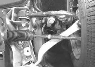
Bottom view of the right front wheel suspension
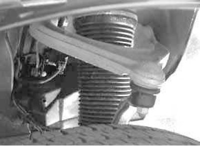
View of the upper suspension arm of the left front wheel
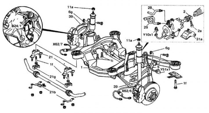
Front wheel suspension elements
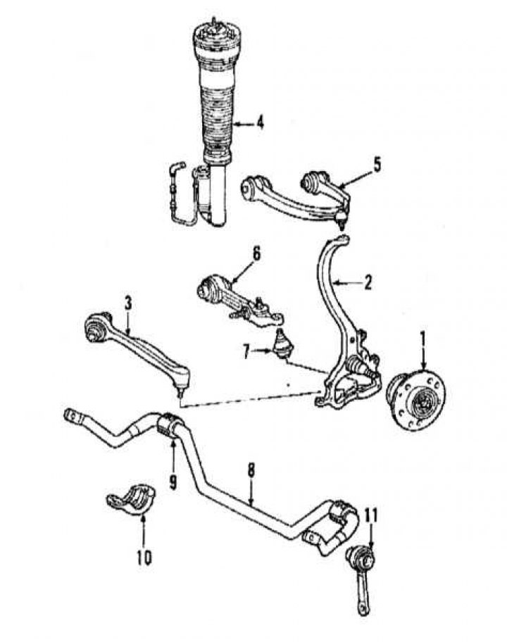
1 - wheel hub; 2 - rotary fist; 3 - spacer; 4 - depreciation air suspension strut; 5 - upper suspension arm; 6 - lower suspension arm; 7 - ball bearing; 8 - stabilizer bar; 9 - bushing; 10 - bracket; 11 - thrust
Removing the suspension strut
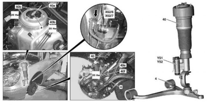
4 - Cross lever; 40 - suspension strut; 40a - Pressure line connection; 40b - Nuts; 40e - C-bracket; 40f - Screws; X62/6 - Right front drive shaft connector, main assembly compartment; X62/7 - LH front drive shaft connector, main assembly compartment; Y51 - Left front drive shaft damping valve block; Y52 - Block damping valve right front drive shaft; a - Residual pressure valve; Arrow - Spring
Removal and installation of a forward suspension bracket
Removing
1. Remove the front wheels.
2. Install protective plates for the rubber boots of the brake calipers.
3. Remove the front springs.
4. Disconnect connectors X62/6 or X62/7.
5. Disconnect connector Y10/1 at the front left of the P-valve.
6. On models with automatic differential lock ASD: Disconnect the connection from damper valve Y51/12.
7. Disconnect all plastic front suspension covers.
8. Raise the engine.
9. Disconnect the stabilizer bar mounting bracket 21b.
10. Turn away a brake tube 39 from a brake line.
11. Disconnect a rotary fist 5 from the top lever.
12. Remove the heat shield 31 a on the steering gear.
13. Raise the front suspension brackets.
14. Disconnect the engine mounts from the front suspension.
15. Remove the plastic cover 21g, disconnect the front beam 1 and remove the brackets 21.
16. Disconnect the supply 29 and drain 28 pipelines.
17. Lower the front suspension brackets.
18. Remove the upper arm.
Installation
Installation is carried out in the reverse order of removal.