



Contents: General information ↡ Front suspension ↡ Rear suspension ↡ Steering ↡ Suspension Geometry ↡ Tightening force of threaded…↡
Note: Individual characteristics are also given in the text of the Chapter and, if their implementation is mandatory, are highlighted in bold.
General information
| Wheelbase, track, turning diameter, mm | Cm. Specifications |
| Steering gear designation | 765.503 |
Front suspension
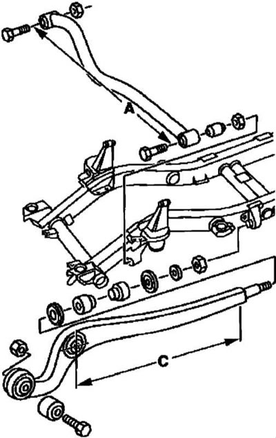
| Design: | Independent with a solid axle, organized by means of telescopic shock absorbers, separately installed coil springs, longitudinal levers, diagonal rod and anti-roll bar (torsion bar) (see illustrations Front suspension organization diagram and Front Axle Installation Details) |
| Control dimensions of the diagonal rod and longitudinal suspension arms, mm | |
| 760±0.5 |
| 706 |
Rear suspension
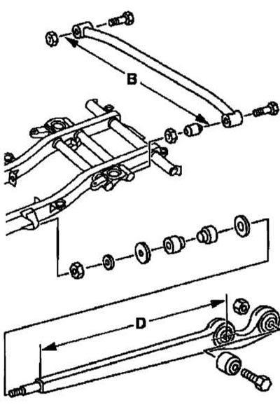
| Design: | Independent with a solid bridge, organized similarly to the front (see illustrations Rear suspension organization diagram and Rear Axle Assembly Installation Details) |
| Control dimensions of the diagonal rod and longitudinal suspension arms, mm | |
| 760±0.5 |
| 706 |
Steering
Design
| Drive | Hydraulically amplified worm gear with recirculating balls and steering trapezoid |
| Steering column | Trauma-safe, telescopic, with a landing offset function and tilt adjustment |
| Power steering fluid type and volume | Cm. Specifications |
Steering pump
Petrol models
| Models released on 02.10.00 | 67 (ZF) |
| Models produced from 03.10.00 to 27.09.00 | 67 (ZF) |
| Models released from 28.09.00 | VDA LF30(LUK) |
Diesel models
| Models 463.323 | 67 (ZF) |
| Models 463.333 | |
| 67 (ZF) |
| VDA LF30 (LUK) |
Pressure in the power steering system, atm
| Pump 67 (ZF) | |
| 82±5 |
| 105±5 |
| Pump VDA LF30 (LUK) | 105±5 |
| Frictional resistance of steering gear rotation in central position, Nm | 1.6 |
| Frictional resistance of rotation of balls in the central position, Nm | 0.6 |
| Frictional resistance of the worm rotation in the bearing cap before setting the preload of the latter, Nm | 0.16 |
| Frictional resistance of the worm rotation in the bearing cap after setting the preload of the latter, Nm | 0.1 |
Suspension Geometry
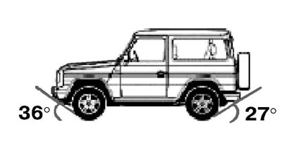
| Front and rear overhang angles | |
| 5 |
| Wheelbase | |
| Cm. Specifications |
| Maximum permissible difference between the bases of the right and left wheels, mm | 5 |
| Overhang angle | |
| 36° |
| 27° |
Dimensional characteristics for checking chassis geometry (models with wheelbases 2400 and 2850)
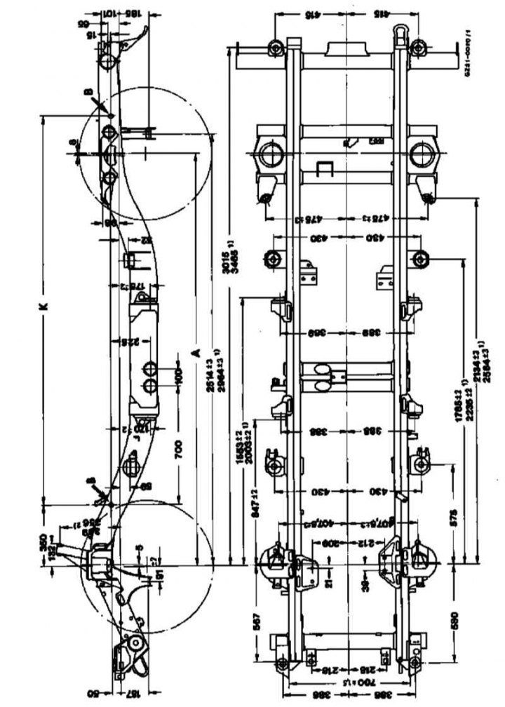
Measurement points
1) - Wheelbase 28500
2) - On the right side of the road
A - Wheelbase
B - Control socket
K - Distance between control sockets 2320 or 2770
Wheel alignment angles
| Convergence | |
| 0° ±16' |
| 0° ±10' |
| Collapse (not regulated) | |
| 1° ±30' |
| 0° +20'/-40' |
| Run-out | |
| Required value | Determined by nomograms (see accompanying illustrations) |
| Permissible difference between right and left wheel | 30' |
| Kingpin/wheel pivot angle (not regulated) | 9° ±5' |
| Front wheel turning angle limits (inner wheel) | 35°30' ±30' |
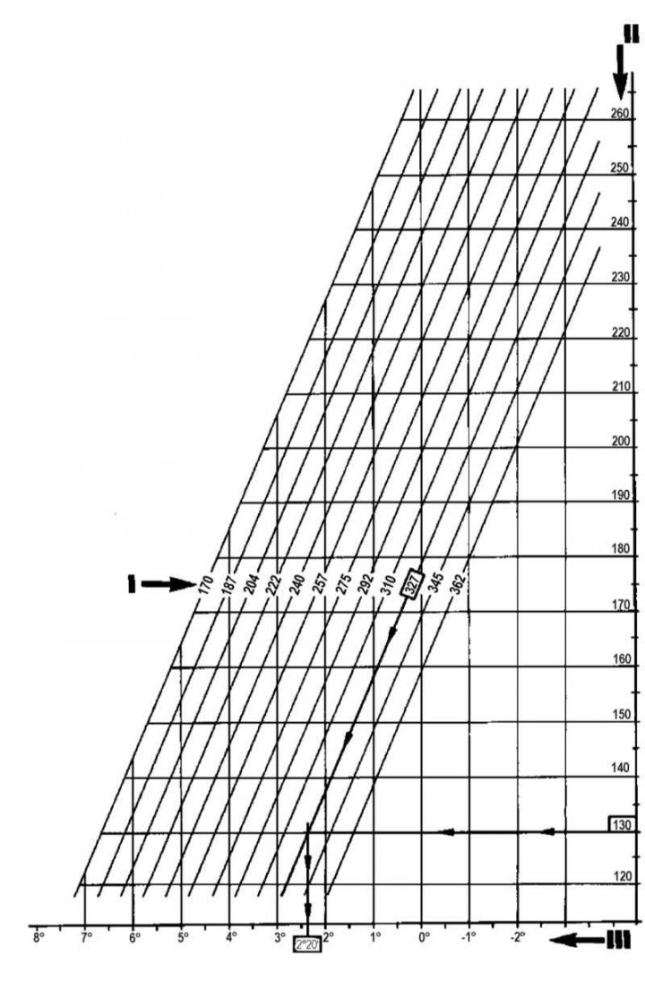
Nomogram for determining coastdown on models with a wheelbase of 2400 mm
I — Distance between the center of the bolt of the longitudinal arm on the rear axle and the lower edge of the beam (see Section Determining the required amount of run-out)
II — Distance between the center of the trailing arm bolt on the front axle and the lower edge of the frame (see Section Determining the required amount of run-out)
III — Required run-out value
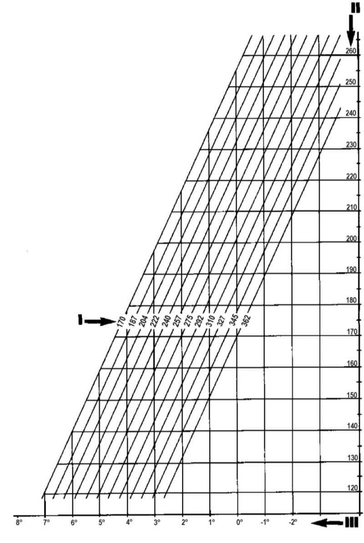
Nomogram for determining coastdown on models with a wheelbase of 2850 mm
I — Distance between the center of the bolt of the longitudinal arm on the rear axle and the lower edge of the beam (see Section Determining the required amount of run-out)
II — Distance between the center of the trailing arm bolt on the front axle and the lower edge of the frame (see Section Determining the required amount of run-out)
III — Required run-out value
Tightening force of threaded connections, Nm
Front suspension
| Nuts securing shock absorbers to front axle assembly | 70 |
| Nuts for fastening the anti-roll bar to the struts | 90 |
| Nuts securing the stabilizer bar struts to the frame | 90 |
| Nuts for fastening the stabilizer bar clamps to the trailing arms | 70 |
| Nuts for fastening the diagonal rod to the frame | 130 |
| Bolts/nuts for fastening the longitudinal arms to the bridge | 210 |
| Nut for fastening the diagonal rod to the frame | 210 |
Rear suspension
| Nuts securing the trailing arms to the frame | 130 |
| Nuts for fastening the longitudinal arms to the bridge | 210 |
| Nuts for fastening the diagonal rod to the frame | 210 |
| Nuts for fastening the diagonal rod to the bridge and frame | 210 |
| Bolts for fastening the transverse levers to the bridge | 210 |
| Bolts (M16x1.5-8.8) fastening shock absorbers to the bridge | 100 |
| Bolts (M14x1.5-8.8) fastening shock absorbers to the frame | 70 |
| Bolts (M12) for fastening the anti-roll bar to the struts | 90 |
| Bolts (M10) for fastening the stabilizer bar clamps to the trailing arms | 70 |
Steering
| Fastening the expansion hose of the pressure tract to the steering pump | |
| |
| 30 |
| 40 |
| |
| 45 |
| |
| 30 |
| 40 |
| Steering wheel to steering shaft mounting bolts | 80 |
| Pin for fastening the electronic lock to the steering column housing | 10 |
| Steering column housing mounting bolts to support brackets | 20 |
| Bolts for fastening the distance tube to the steering column housing and instrument panel support | 20 |
| Nut securing the central cardan joint to the steering shaft | 38 |
| Bolt M8 for fastening the universal joint | 35 |
| Steering pump mounting bolts | |
| 20 |
| |
| 20 |
| Fasteners to the timing belt cover (self-locking screw) | |
| 35 |
| 20 |
| Bolt securing reservoir to steering pump | 8 |
| Steering pump drive pulley mounting bolt | 20 |
| Bolt for fastening the bearing flange to the steering pump | 35 |
| Castle nuts for fastening the transverse rod to the steering arm and the steering knuckle | 140 |
| Tie rod end tightening bolt | 55 |
| Steering gear mounting nut for steering arm | 400 |
| Steering gear to frame mounting bolts | |
| 50 |
| 100 |
| Nut in the steering gear working piston | 240 |
| Bolts securing the cover to the steering gear housing | 65 |
| Bolt securing the locking tongue to the steering gear housing | 10 |