
Accelerator pump adjustment
Press the accelerator pump lever several times. There should be strong jets of fuel (see arrows in fig. 120). If they are not available, do the following:
Remove the accelerator pump cover.
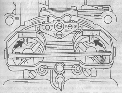
Pic. 120. Checking the accelerator pump.
Check the condition of the diaphragm and blow out the intake and discharge channels.
Assemble the accelerator pump. If fuel does not flow when the pump is pressed, remove the carburetor cover and check the operation of the accelerator pump again. When fuel appears in both valves, it is necessary to blow out the injection holes in the carburetor cap with compressed air.
Check valve check
Disconnect hose from fuel return line (below fuel pump). Lower the hose into a container and check the fuel flow at idle speed, at various positions of the automatic transmission control lever and with the air conditioner on.
Checking the damping actuator 2nd stage
Start the engine at idling speed and bring the diaphragm of the pneumatic actuator to the stop against the housing. Pinch the hose, open and close the air damper several times. The diaphragm should always return to its original position with a characteristic sound. If the diaphragm rises when checking, it is a sign of leakage and the diaphragm must be replaced.
Adjustment of idling and composition of exhaust gases to the level of CO emissions
A protective seal is installed on the idle speed adjusting screw, which protects against unqualified idle speed adjustment. The adjustment of the composition of the mixture can also be sealed. On fig. 121 arrows show the meta location of the seals. On this basis, adjustment work must be carried out at a service station. In the absence of a seal and with appropriate experience, the idling speed is adjusted as follows:

Pic. 121. Places for installing seals on the screws for adjusting the composition of the mixture (left arrow) and idle speed (right arrow).
Start the engine and warm up to operating temperature. Check that the air damper is fully open. Check for ease of rotation of the throttles. To do this, by turning the throttle lever, increase the speed to 2000... 25000 rpm and release the lever. The lever should automatically return to its original position.
Connect the tachometer and CO meter according to the instructions for use.
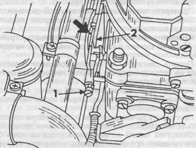
Start the engine and note the tachometer reading. If the rotational speed is not within 800... 900 rpm, adjust the screw (2), as shown in fig. 123. On the other hand to remove shown on fig. 120 cap - seal and adjust the idle speed accordingly. Place a new filling after adjustment (part N 000 988 513 5). Check the position of the throttle lever, it should reach the stop and not touch the vacuum regulator. If necessary, loosen the vacuum regulator spring by turning the nut (1) (see fig. 123).
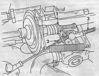
Pic. 123. Adjusting the idle speed.
1 - adjusting nut,
2 - idle speed adjustment screw,
3 - traction adjustable.
Determine the CO content using the instrument. To do this, connect the device to the terminals on the two exhaust pipes, if any (see fig. 122), otherwise, connect the device in accordance with its instruction manual. When checking, do the following:
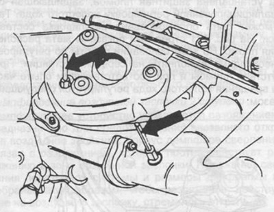
Pic. 122. Arrows show two outputs for measuring CO content. The conclusions are plugged with plugs, which must be removed before changing.
Start the engine and read the instrument readings. Readings should be within 2.5%.
If necessary, remove the seals from the adjusting screws as shown in fig. 124, and turn both screws to the right as far as they will go. Then turn the screws to the left by the same angle until the desired CO value is reached. When unscrewing, the mixture is enriched, when wrapped, it is depleted.
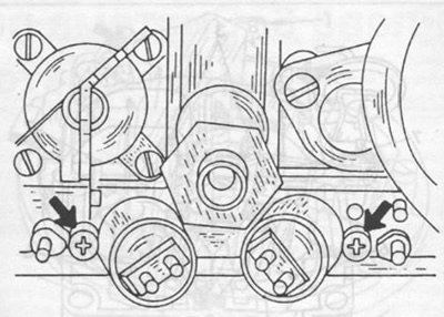
Pic. 124. The arrows show the adjusting screws for adjusting the composition of exhaust gases at idle.
Check idle speed and adjust if necessary. After adjustment, check the CO content in the exhaust gases again. Install new seals.
Adjustment of drafts of a drive of giving of fuel
For vehicles with manual transmission:
Start the engine at idle speed.
Adjust the length of the drive rod so that the rocker arm roller reaches the stop without tension.
For vehicles with automatic transmission (see fig. 125):
Start the engine at idle speed.
Remove traction (1) automatic transmission pressure control.
Push back on the angle lever as shown in fig. 125.
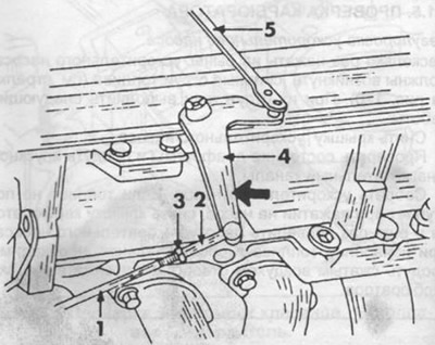
Pic. 125. Pressure control rod.
1 - pressure control rod,
2 - tip of the ball joint,
3 - locknut,
4 - angle lever,
5 - intermediate thrust.
Press the linkage of the automatic transmission back as far as it will go and adjust, if necessary, the position of the tip of the ball joint so that it fits freely on the angle arm support.
Check the length of the adjusting rod and intermediate rod. The length of the adjusting rod must be 120 mm and the connecting rod 309 mm. The measurement is taken between the centers of the hinges.
Checking the full load stop
For this check, the 2nd stage locking device must be released. Press down on the stop on the stepped spacer with the counterweight of the starting automation. Press the fuel pedal all the way down. In this case, the throttle levers must also reach the limit stop. If necessary, adjust the position of the lever after loosening the mounting bolt in the engine compartment (see fig. 126).
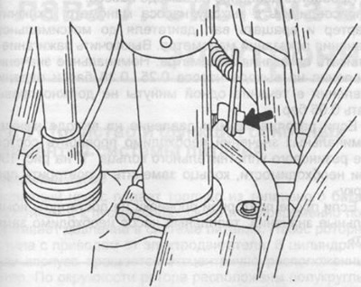
Pic. 126. Full load stop adjustment.
Vacuum regulator adjustment
Before starting work, adjust the idle speed and warm up the engine. The engine is idling.
Disconnect the hose from the regulator.
Adjusting bolt (5) in fig. 127 increase the speed to 1600 rpm.
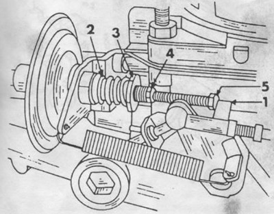
Pic. 127. Adjustment of the vacuum regulator.
1 - throttle lever,
2 - spring,
3 - adjusting nut,
4 - locknut,
5 - adjusting bolt.
Attach hose.
Loosen locknut before adjusting (4), while holding the diaphragm rod from turning with a key. If the diaphragm rod is poorly fixed, this indicates damage to the diaphragm in the regulator housing.
Adjust spring force:
Automatic transmission
Place the transmission control lever in the drive position. The rotational speed should be within 600... 700 rpm. Adjust spring force (2) with a nut (3) for this rotational speed. Then turn the front wheels of the car to the stop and turn on the air conditioner. Repeat the adjustment if necessary.
Manual Transmission
The engine is running at idle speed. Adjust the spring force with a nut so that there is a gap of 1.0 mm between the head of the adjusting bolt and the throttle lever.
Starter adjustment
Check the ease of rotation of the starting damper.
Switch on the ignition and check the opening time of the starting damper.
Check starter cover adjustment. The marks on the body and the lid must lie on the same line.
Start the engine at idling speed until the diaphragm stops in the pneumatic drive housing under the action of vacuum.
Put a clamp on the hose and pinch the hose.
Stop the engine and check the diaphragm travel time.
Raise the throttle lever and move the stepped spacer up to the stop. Release the throttle lever.
Use a screwdriver to press until a noticeable stop on the lever of the bimetallic spring. Insert the end of the rod into the hole in the lever. Slightly lower the lever until the diaphragm acts on it.
Using a rod or drill with a diameter of 1.5 mm, check the gap between the lower open edge of the starting damper and the carburetor wall. To adjust the gap, remove the rear coolant supply hose from the starter automatic housing. Use a screwdriver to hold the rod and use a second screwdriver to bend it, as shown in fig. 128. If the gap is large, the rod must be straightened; if it is small, it must be bent. In the process of adjustments, check the position of the diaphragm; it must be pressed against the body as far as it will go. If not, the diaphragm or hose is leaking and needs to be replaced.
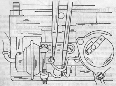
Pic. 128. Adjustment of the starting damper.
Check cold start speed and adjust if necessary. Work is carried out on a warm engine with an adjusted idle speed.
- start the engine at idle speed.
- raise the lever and press the stepped spacer up to the stop, release the throttle lever.
- measure the rotational speed, if necessary, adjust the screw. Cold start speed 2400...2600 rpm (see fig. 129).
- in carburetors of the second version, adjustment is made using a screw located in the cover of the starting device. In carburetors with a TN device, cold start speed adjustment is not required, because. throttle control is performed by a vacuum regulator. Adjusting screw "1", shown in fig. 129 is therefore not set.
Pic. 129. Adjustment of rotational speed at cold start.
1 - adjusting screw,
2 - step spacer.