
Checking and setting the level in the float chamber
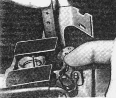
1. Remove the carburetor.
2. Remove the solenoid valve.
3. Remove the float chamber, jet and spring.
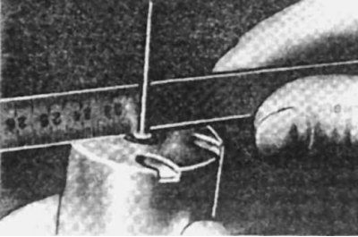
4. Turn the carburetor over and measure the distance between the highest point of the float and the plane of the float chamber, which should be 17±0.5 mm.
5. If necessary, adjust the size by bending the float lever.
6. Install float chamber, jet and spring.
7. Install the solenoid valve.
8. Install the carburetor.
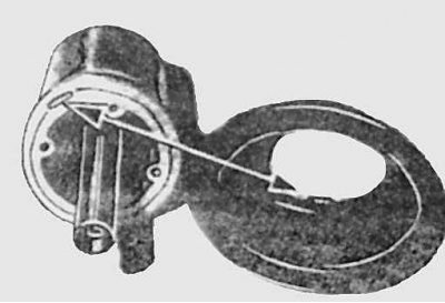
Checking the dispensing needle
The needle moves freely in the holder and must therefore be in a strictly defined position. Its surface is processed with high precision, and the slightest wear worsens the dosage and atomization of the fuel; it should not have smoothed areas. The holder is attached with a conical screw adjacent to the flat. The plastic washer must be in the same plane as the bottom of the piston.
Checking the needle setting
Diaphragm check
The diaphragm must be intact, without damage, and correctly fit to the bearing surfaces, and the mounting grooves to the bearing lugs. Check the position of the mounting groove.
Membrane installation
Throttle start gap adjustment
1. Without disconnecting the engine cooling system hoses, unscrew the three screws securing the thermostat and remove it from the carburetor.
2. Remove the throttle return damper.
3. Turn off the adjusting screw of quantity of a mixture before full closing of a butterfly valve.
4. Disconnect the throttle lever.
5. Mark the throttle angle.
6. Turn the mixture adjustment screw until the throttle valve opening angle reaches 6°.
7. Install the lever.
8. Open the throttle to the maximum with the lever.
9. Release the lever and check the throttle position, which should be 16°±1 or 0.65±0.05 mm.
10. If abnormal, adjust the lever.
11. Install and adjust the throttle return damper.
12. Install the thermostat, observing its adjustment.
Throttle damper adjustment
1. Start the engine at idle, disconnect the vacuum hose and adjust the starter screw to set the engine mode to 1200-1400 rpm.
2. Connect the vacuum hose.
3. Check the gap between the adjusting screw and the throttle control lever, which should be 0.5 mm.
Scheme of connecting vacuum hoses on a Stromberg carburetor
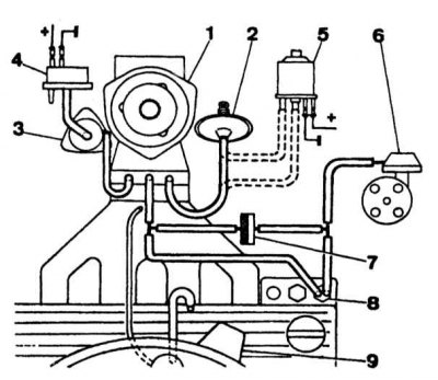
1 - carburetor; 2 - pneumatic return to idle; 3 - starting device; 4 - thermoelectric valve; 5 - solenoid idle control valve on vehicles with air conditioning; 6 - vacuum corrector of the ignition distributor sensor; 7 - check valve; 8 - thermostatic valve of the vacuum corrector of the ignition distributor; 9 - air filter
Thermostat adjustment
1. Pinch the heating hoses and disconnect them from the thermostat.
2. Disconnect the block and remove the thermostat assembly.
3. Heat the thermostat cover to 20°C.
4. Install the cover with gasket on the body of the starter.
5. Turn the cover clockwise until the lever is in the middle of the 2nd profile of the throttle opening sector.
6. Mark the relative position on the cover and on the body of the starter. Remove old labels if necessary.
7. Install thermostat.
8. Attach block.
9. Attach heating hoses and remove air from the engine cooling system.
Quality control (composition) fast idle mixture
1. Warm up the engine.
2. Remove the trigger box protective cover.
3. Slightly open the throttle and place the piston control lever on the 2nd sector profile at the level of the throttle control lever.
4. Start the engine.
5. Use the secondary air adjusting screw to achieve the desired carbon monoxide content (SO) in exhaust gases.
Engine idle and carbon monoxide adjustment (SO) in exhaust gases
1. Warm up the engine.
2. Make sure the throttle does not hit the return shock or the fast idle control lever at idle.
3. With the adjusting screw of the control lever, achieve the normal frequency of the crankshaft at idle.
4. Check and, if necessary, adjust the carbon monoxide content (SO) in exhaust gases. To do this, remove the plug from the solenoid valve and unscrew it to increase the CO content and vice versa.