
O-rings must be replaced with new ones after disassembly.
Do not use pistons and cylinders with worn, damaged or oxidized working surfaces. Install only new cylinder assemblies.
Only use the prescribed brake fluid, do not use older brake fluid.
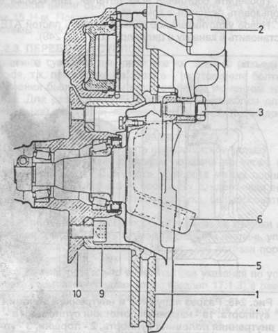
Pic. 247. Section of the brake disc, pistons and caliper.
1 - brake disc,
2 - support,
3 - fastening bolt,
5 - protective cover,
6 - pivot pin,
9 - a bolt with an internal hexagon,
10 - front wheel hub.
Pistons and O-rings (cuffs) lubricate with either clean brake fluid or brake grease. The most suitable grease recommended by the manufacturer of the brake equipment.
The halves of the caliper should not be separated during disassembly, because when assembled at the factory, the mounting bolts were tightened to a specific tightening torque.
Remove the brake pads as described above.
Remove the dust ring using a screwdriver.
Using pliers, hold the piston in the caliper and press out the opposite piston with compressed air (see fig. 248).
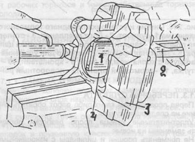
Pic. 248. Removing the pistons from the caliper.
1 - rubber pad on slots,
2 - slots,
3 - support,
4 - pistons.
Remove the piston seal from the groove in the cylinder. Press out the second piston.
Check the condition of all parts. For assembly, use repair kits.
Lubricate the new sealing ring with ATE paste and install in the groove in the cylinder (see fig. 249).
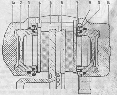
Pic. 249. Section of the outer and inner halves of the caliper.
1a - outer half of the caliper,
1c - inner half of the caliper,
2 - pistons,
3 - piston sealing ring,
4 - brake shoe,
5 - brake pad fastening pin,
6 - brake disc,
7 - heat-insulating screen,
8 - clamping ring,
9 - dustproof ring.
Insert pistons into cylinders.
Use a template to check the position of the piston in the caliper, as shown in fig. 250. If necessary, turn the piston.
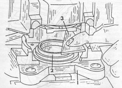
Pic. 250. Template for checking the position of the piston.
1 - support,
2 - piston,
3 - template.
Put the dust cap on the collar of the caliper and press it onto the caliper with a force of 300 N using a hand press.
Install the heat shield on the piston so that the cutout of the shield is aligned with the protrusion of the piston.
Using special tool 000 589 496 300 in the caliper, press the heat shield into the piston. The protrusion of the piston must be at least 0.1 mm above the screen surface. The screens for the outer and inner pistons are different.
Install the brake pads as described in the appropriate section.