



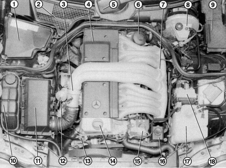
Fig. 4.5. Engine compartment with diesel engine 300 D: 1 – cooled plastic box for electronic controllers and relay units; 2 – air intake grille for interior ventilation; 3 – pressure control valve body; 4 – cover of the injector and spark plug compartment; 5 – windshield wiper drive; 6 – oil filter; 7 – intake manifold; 8 – brake fluid reservoir with master cylinder and brake booster; 9 – fuse and relay box; 10 – expansion tank; 11 – air filter; 12 – exhaust system bypass valve; 13 – oil dipstick; 14 – oil filler cap; 15 – petrol filter; 16 – spare capacity of hydraulic oil for servo control; 17 – washer reservoir (front – for headlights, rear – for windshield wiper); 18 – brake block
In addition to the 5-cylinder turbo engines, Mercedes offers a 6-cylinder diesel engine with a cylinder capacity of 3 liters (OM 606) (Fig. 4.5). Technically, the OM 606 is almost completely identical to the OM 604 and OM 605 models with a smaller number of cylinders (2.5 l, 5 cyl.). It is equipped with a cylinder head with a pre-chamber and four valves per cylinder, electronic control, in-line fuel injection pump, dual mass flywheel (for models with manual transmission). The crankshaft of the 6-cylinder engine is mounted on seven support bearings. An exclusive feature of the OM 606 is the adjustable length intake manifold in the form of a three-stage resonant intake manifold with flaps.
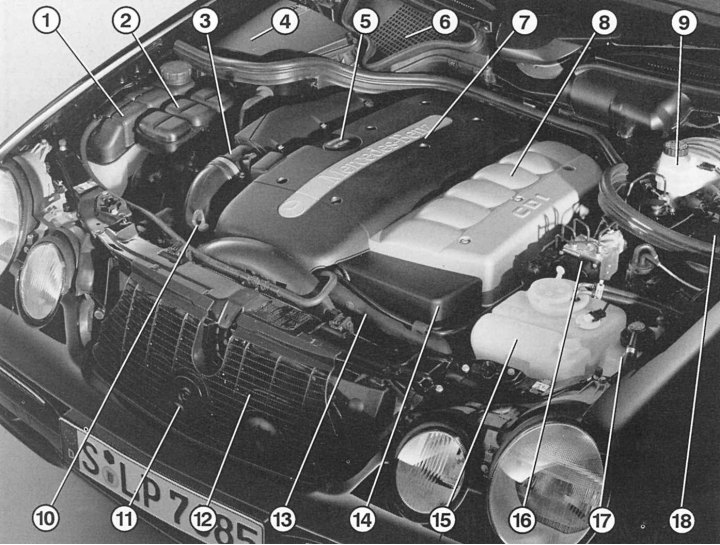
Fig. 4.6. Engine compartment with diesel engine 320 CDI: 1 – expansion tank; 2 – air filter; 3 – turbocharger air supply channel; 4 – cooled box for electronic controllers and relay units; 5 – oil filler cap; 6 – air intake grille for interior ventilation; 7 – engine cover; 8 – intake manifold cover; 9 – brake fluid reservoir with master cylinder and brake booster; 10 – oil dipstick; 11 – sound signal; 12 – Radiator protective grille; 13 – radiator hose; 14 – petrol filter cover; 15 – washer reservoir (front – for headlights, rear – for windshield wiper); 16 – brake system control unit; 17 – spare hydraulic oil tank with servo regulator; 18 – fuse and relay box
Since August 1999, Mercedes vehicles have been equipped with the 320 CDI engine (Fig. 4.6) with a Common Rail system, replacing the E 300 D.
All CDI engines are modular, have the same distance between cylinders (97 mm) and the same diameters and strokes (88 x 88.34 mm). At the same time, CDI engines received a new cylinder head with four valves, centrally located injectors and an aluminum construction.
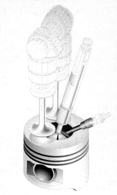
Fig. 4.7. Fuel distribution in the combustion chamber
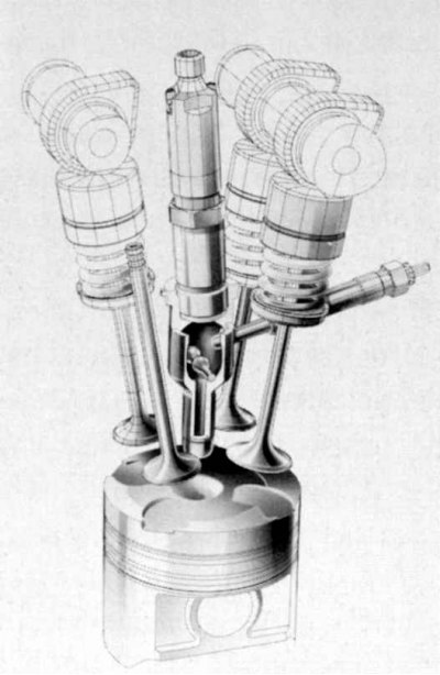
Fig. 4.8. Multi-valve system
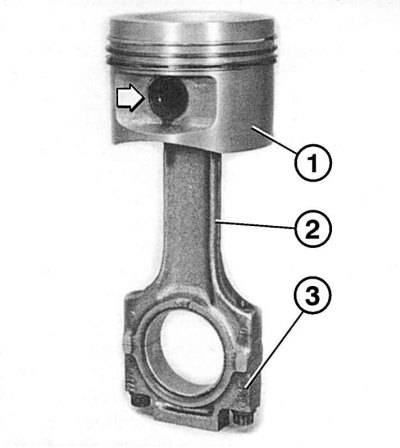
Fig. 4.9. Piston with connecting rod: 1 – piston with three piston rings; 2 – connecting rod; 3 – support bearing cover
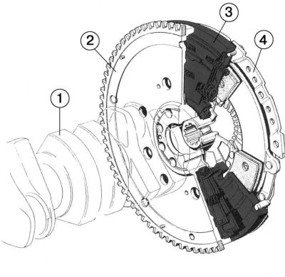
Fig. 4.10. Dual mass flywheel: 1 – crankshaft; 2 – front part of the flywheel; 3 – torsional vibration damper; 4 – rear part of the flywheel
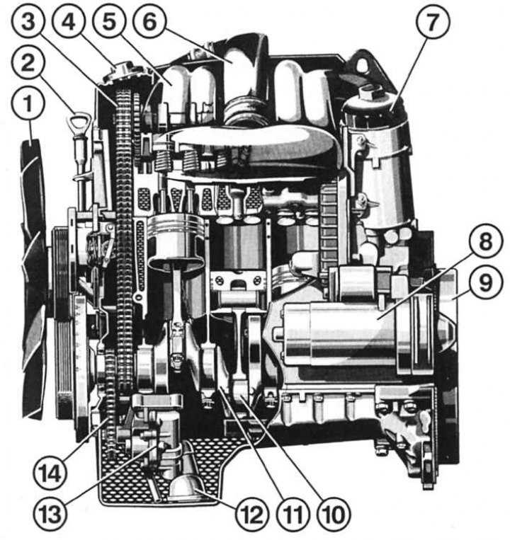
Fig. 4.11. Longitudinal section of a 4-cylinder diesel engine with pre-chamber injection (OM 604): 1 – fan with viscous coupling; 2 – oil dipstick; 3 – camshaft drive chain; 4 – oil filler neck; 5 – intake manifold; 6 – branch pipe from the control valve body; 7 – oil filter; 8 – starter; 9 – dual mass flywheel; 10 – connecting rod with piston; 11 – crankshaft; 12 – oil pump receiving funnel; 13 – oil pump; 14 – oil pump drive chain
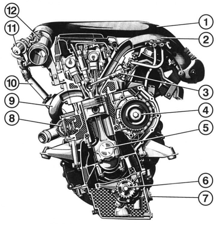
Fig. 4.12. Cross-section of a 4-cylinder diesel engine with pre-chamber injection (OM 604): 1 – intake manifold of the intake system; 2 – intake manifold; 3 – glow plugs; 4 – fuel injection pump drive gear; 5 – connecting rod shafts of the crankshaft; 6 – oil pump drive gear; 7 – oil level sensor; 8 – cooling system thermostat; 9 – outlet pipe; 10 – exhaust gas recirculation channel;11 – exhaust gas recirculation valve; 12 – control valve body
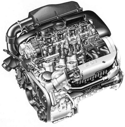
Fig. 4.13. Five-cylinder diesel engine CDI (OM 612)
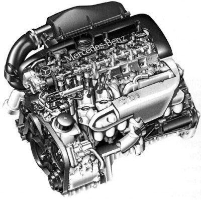
Fig. 4.14. Six-cylinder diesel engine CDI (OM 613)
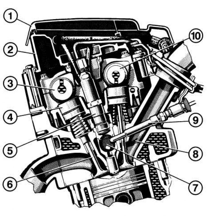
Fig. 4.15. Joint operation of the camshaft and valves: 1 – cylinder head cover; 2 – cylinder head casing; 3 – exhaust camshaft; 4 – tappets with hydraulic clearance adjustment; 5 – injection nozzle; 6 – exhaust valve; 7 – pre-chamber with inlet channel to combustion chamber; 8 – inlet channel; 9 – nozzle; 10 – intake camshaft
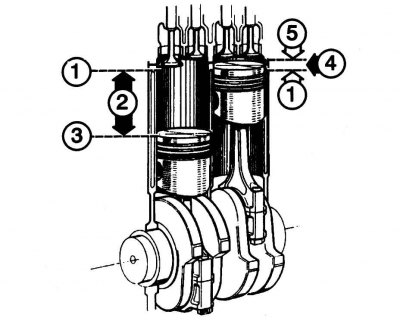
Fig. 4.16. Piston positions: 1 – top dead center; 2 – working stroke; 3 – bottom dead center; 4 – combustion chamber; 5 – cylinder head
(Article text obtained from the website: MercedesMan)
Multi-valve system
Four-valve cylinder head. Engine power depends not only on the cylinder volume and the number of revolutions, but also on the speed of the fuel-air mixture entering the combustion chamber and the speed of exhaust gas release. Therefore, compared to a 2-valve system, a 4-valve system promotes more intensive filling of the combustion chamber (Fig. 4.7). In addition, four valves of a smaller diameter have a much larger opening area than two valves of a larger diameter (Fig. 4.8). Fuel combustion in engines with a 4-valve system is "softer" than in engines with a 2-valve system, since the valves have less inertia. This helps reduce the noise level during operation.
Engine parts
Cylinder block. This is the largest and heaviest unit and contains the crank mechanism. The cylinder block is made of grey cast iron. Inside the block are water cooling channels. At the bottom of the block are the cushions for the crankshaft support bearings. The blocks for the new 5- and 6-cylinder CDI engines are made of grey cast iron. Due to increased mechanical loads (direct injection) the blocks have additional stiffening ribs and thicker walls.
Cylinder head. Closes the block from above. Made of light alloy. Compared to a head made of gray cast iron, there is a higher probability of distortion due to insufficient cooling, improper installation or dismantling of a hot engine, but it is lighter in weight and has a higher heat transfer to the cooling system. The cylinder head has channels for cooling, lubrication, the intake system and the exhaust system. It also has mounting seats for glow plugs, injectors, valves and tappets. The camshafts are located on top of the cylinder head. The pipes are mounted on the outside of the cylinder head. Various sensors, switches and valves are located on the left. The valve seats are made of hard metal. The aluminum cylinder head for CDI engines differs, among other things, in having two spiral intake channels. One of them is used for swirl, the other for filling. Both channels correspond to symmetrically designed combustion chambers and serve to strongly swirl the air in front of the cylinders, which helps to create an optimal mixture of fuel with the injected air. Newly designed injectors located in the middle of the cylinders serve to evenly distribute the fuel inside the combustion chambers.
Cylinders. The cylinders are built into the block and together with the combustion chambers of the cylinder head form the cylinder volume. The inner walls of the cylinders are honed using the so-called mesh grinding method. The cylinder diameters are made 0.02 mm larger than the corresponding pistons. During a major overhaul of the engine, the cylinders can be additionally ground up to 3 times, ensuring the appropriate repair size.
Pistons. They take on the pressure of the burning mixture and transmit the force to the crankshaft via the connecting rod. They are made of light metal. The piston rings are located in the upper third of the piston. The two upper rings (compression) prevent the penetration of gases during operation into the engine crankcase. Lower (oil scraper) the ring removes oil from the cylinder walls.
Connecting rods. Connect the pistons to the crankshaft (Fig. 4.9). The connecting rod head with a bronze insert is connected to the piston using a loosely fitted pin. The connecting rod base is secured to the crankshaft using a support bearing cap.
Crankshaft. Transforms the reciprocating motion of the pistons into rotational motion. To avoid vibration during operation, the crankshafts have counterweights. To prevent uncontrolled vibrations or deflection during operation, the bearing journals of the shaft are mounted with bearings on the engine block. Back (in the direction of movement) a support ring with a toothed rim is installed on the end of the crankshaft to eliminate axial runout of the shaft. Gears for driving the camshaft and oil pump, as well as a pulley for the auxiliary drive belt are mounted on the front end of the crankshaft.
Dual-mass flywheel. Cars with a manual transmission are equipped with a dual-mass flywheel (Fig. 4.10). It smooths out torsional vibrations of the crankshaft that occur during engine operation. The front part of the flywheel is tightly bolted to the crankshaft 1. It has a torsional vibration damper 3, consisting of a system of springs and dampers. The rear part of the flywheel is secured to the torsional vibration damper and is not rigidly connected to the front part and the crankshaft.
The external appearance, sections and details of the engines are shown in Fig. 4.11, Fig. 4.12, Fig. 4.13, Fig. 4.14.
Valves. Through them, the injection of the combustible mixture and the release of exhaust gases are carried out.
Camshaft. With four valves per cylinder, both camshafts are mounted in a special housing.
The camshaft serves to drive the valves in a certain order. The moment of closing and opening is set by setting the crankshaft to a certain position (Fig. 4.15).
The camshafts are driven by a chain from the crankshaft. Both camshafts are gear-engaged with each other. The gear on the camshaft has twice as many teeth as the gear on the crankshaft. The camshafts are of different lengths according to the number of cylinders. To save weight, the shafts are hollow.
Basic concepts of engine operation
Four-stroke principle of operation.
Intake (1st stroke): the piston moves down to the bottom dead center; the inlet valve opens and the forced air is supplied to the cylinder.
Compression (2nd stroke): the piston moves from bottom dead center to top dead center; inlet valve closed; under the pressure of the piston the air is compressed.
Combustion (3rd stroke): the compression temperature ignites the fuel, the fuel mixture during combustion pushes the piston to the bottom dead center, and the connecting rod turns the crankshaft.
Exhaust (4th stroke): the piston goes up again, the exhaust valve is open, and the exhaust gases go into the exhaust system.
The working volume of the cylinder. The volume of the cylinder at which the piston passes from the bottom dead center to the top is called the working volume. When the piston reaches the top dead center, there is still a small space of the combustion chamber. The combustion chamber and the working volume are shown in Fig. 4.16.
Compression ratio. This is a characteristic of the relationship between the working volume of the cylinder and the volume of the combustion chamber. It shows how many times the combustible mixture is compacted before ignition.
Attention! Repair of engine units and parts requires high qualifications and special tools. All work must be carried out exclusively at specialized service stations.