
Ignition coils
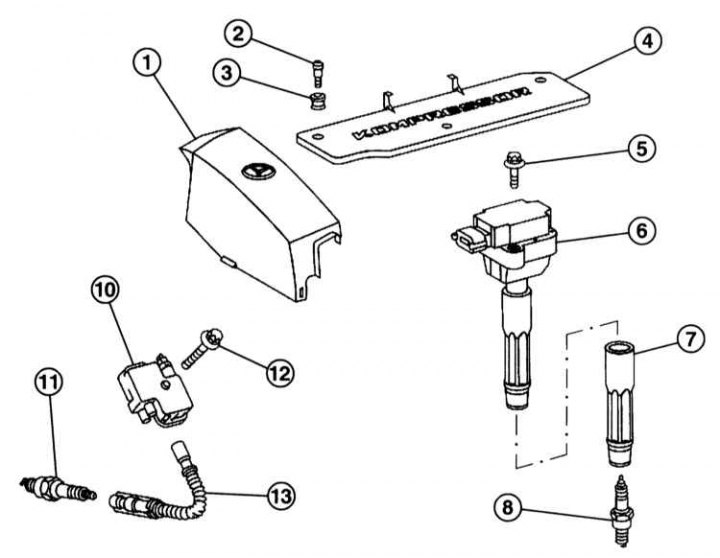
4-cylinder petrol engine
1 - Front cover of the engine; 2 - Bolt; 3 - Spacer; 4 - Cover of ignition coils; 5 - Bolt M6x25, 9Nm; 6 - Ignition coil; 7 - Spark plug plug; 8 - Spark plug: Engine 111: 28Nm, Engine 271: 25Nm
6-cylinder petrol engine
10 - Ignition coil; 11 - Spark plug, 28Nm; 12 - Bolt, 8Nm; 13 - Ignition cable with spark plug plug, from ignition coil to spark plug
The layout of the components of control systems. Models C240 and C320
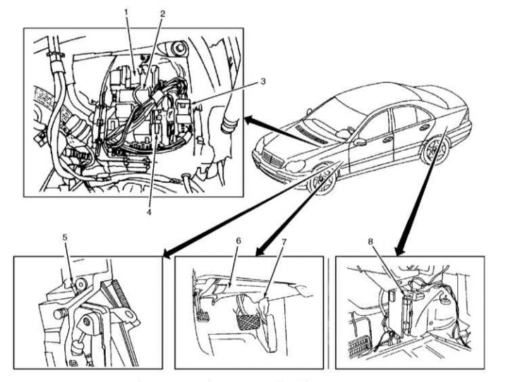
1 - Front control unit for signal selection and registration (SAM) with relay/fuse box and secondary air mixing system relay; 2 - Fan relay module; 3 - ECM; 4 - SAM control unit with relay/fuse box and starter relay; 5 - Clutch pedal switch; 6 - DLC connector; 7 - Pedal position sensor; 8 - Rear SAM control unit with relay/fuse box and fuel pump relay
The ignition system generates sparks that ignite the intake air-fuel mixture. To do this, the 12 V voltage is converted in the ignition coils to a voltage of 30,000 V.
The electronic direct ignition system is part of the engine management system and includes spark plugs as well as ignition coils with built-in spark plug plugs. On a 6-cylinder engine, the ignition coils and spark plug plugs are connected by a short cable.
The distribution of the ignition current over the candles is controlled by the electronic control unit.
There is no external adjustment of the ignition timing. If the ignition timing deviates from the specified value, it is necessary to replace the damaged elements.
The ignition system does not wear out and does not require maintenance. The maintenance schedule only requires replacement of the spark plugs.
Basic information on the operation and sensors of control systems and injection of gasoline and diesel engines is described in Section Functioning of the control system and injection of a gasoline engine.
The main elements of electrical equipment, the location of ignition and fuel injection control units, sensors, valves and drive elements are shown in the accompanying illustrations.
Safety measures when working with the ignition and injection system
To prevent personal injury and/or damage to the injection and ignition system, the following must be observed:
- Do not touch or disconnect the ignition wires while the engine is running or the starter is engaged.
- Disconnect and connect the pipelines of the injection system and the ignition wires, as well as the electrical wires of the measuring instruments only with the ignition off.
- Do not allow people with a pacemaker to operate the electronic ignition system.
- Do not ground terminal 1 of the ignition coils.
- When working with engine cranking speed, such as when checking compression pressure, turn off the ignition and disconnect the crankshaft position sensor connector.
- Do not connect a test lamp to terminal 1 of the ignition coils.