
Location of components in the engine compartment of models C240 and C320
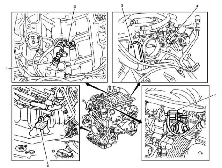
1 - Knock sensor (KS) 1 (Right side of the engine); 2 - Knock sensor (KS) 2 (Left side of the engine); 3 - Throttle position sensor (TPS); 4 - EGR vacuum transmitter; 5 - Valve-switch for the configuration of the inlet pipeline; 6 - Temperature / quality / oil level sensor
Fuel is drawn from the fuel tank by the electric fuel pump and fed through the fuel filter to the fuel distribution line. The pressure regulator ensures that the pressure in the fuel system is maintained at 3.2–3.6 atm.
Through electrically controlled injectors, fuel is injected in pulses into the intake manifold located directly in front of the engine intake valves. The engine control unit performs sequential control of the injectors in accordance with the ignition order, regulates the injection time and thus the amount of injected fuel.
The air necessary for the formation of the fuel mixture is sucked in by the engine through the air filter and enters through the throttle valve and intake pipe to the intake valves. The amount of air intake is controlled by a throttle valve, which is moved by a stepper motor controlled by the engine control unit. For compressor engines, the intake air is compressed by a compressor driven by a V-belt. The compressed air is then cooled in the charge air cooler and enters the engine to form the fuel mixture.
The intake air volume is determined by the air quantity meter. The meter is located in the intake air duct. In the meter housing there is a thin, electrically heated sensor plate, cooled by the passing flow of intake air. The electric current heating the plate is regulated by the control system in such a way as to keep the temperature of the plate constant. If, for example, the amount of intake air increases, the temperature of the heated plate starts to decrease. At the same time, the magnitude of the electric current immediately increases in order to keep the temperature of the plate unchanged. Fluctuations in the electric current of the plate indicate to the engine control unit its load condition, which allows it to correctly determine the amount of fuel injected.
The engine control unit is located in the electronics box, on the left, near the brake fluid reservoir or directly on the engine. The control unit determines the optimal ignition timing, injection timing and the amount of injected fuel. In this case, the operation of the control unit is coordinated with other vehicle systems, for example, with the control of the gearbox or the anti-theft system.
Information from other sensors and control voltages supplied to the executive bodies ensure optimal engine operation in any situation. If some sensors fail, the control unit switches to the emergency program mode in order to exclude possible damage to the engine and ensure the further movement of the car. In this case, the engine runs unevenly and tends to stop when the gas is increased.
Sensors and executive bodies of the injection system
The crankshaft position sensor is screwed into the cylinder block at the flywheel. It transmits to the control unit information about the engine speed and the TDC position of the piston of the first cylinder.
The camshaft position sensor is located at the end of the cylinder head cover. Together with the crankshaft position sensor, it transmits to the control unit information about the TDC of the piston of the first cylinder. It serves to synchronize the ignition timing and ignition sequence.
The throttle actuator consists of an electric motor and two potentiometers. It controls the throttle position. This achieves a stable idle speed, regardless of the connection of additional consumers, such as power steering or air conditioning compressor.
The throttle potentiometer is located in the throttle actuator and provides the control unit with information about the current throttle angle. The second potentiometer informs the control unit about the base value and generates a spare signal when the throttle potentiometer fails.
The gas pedal sensor is located in the area where the driver's feet are located directly on the axis of the gas pedal. It informs the control unit about the position of the pedal. For safety reasons, an additional signal is taken from the pedal sensor, in the same way as from the throttle potentiometer.
The coolant temperature sensors are located in the thermostat housing. It is an NTC resistor whose resistance decreases with increasing temperature.
The intake air temperature sensor is also an NTC resistor.
The fuel tank ventilation system consists of an adsorber and a solenoid valve. The adsorber accumulates fuel vapors formed as a result of fuel heating. When the engine is running, the vapors are sucked out of the adsorber and fed into the combustion chambers of the engine.
lambda probes (oxygen sensors) they measure the oxygen content in the exhaust gases before and after the catalytic converter and transmit the corresponding signals to the engine control unit. One lambda probe is located before and the other after the catalytic converter.
The knock sensor is screwed into the cylinder block, next to the guide tube. It prevents the occurrence of dangerous impact combustion of the fuel mixture. Thanks to this, the ignition timing can be kept at the detonation limit, which ensures efficient use of the energy of combustion of the fuel and thus reduces fuel consumption.