



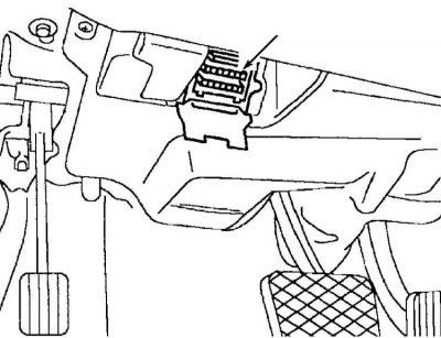
Location of the 16-pin diagnostic connector
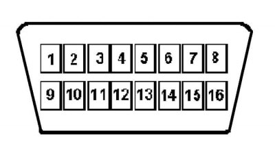
16-pin OBD II diagnostic connector
Pin assignment of the 16-pin diagnostic connector
(Full article available on the resource: «Mercedesman.ru»)
| Output No | Purpose |
| 1 | — |
| 2 | — |
| 3 | TNA signal |
| 4 | Connection to the body, cl. 31 |
| 5 | Housing - signal output, cl. 31 |
| 6 | CAN data bus high level |
| 7 | Engine Electronics (ME) |
| 8 | Nutrition, class 87 |
| 9 | Traction and stability control system (ETS) |
| 10 | — |
| 11 | Transmission Control Unit (ETC) |
| 12 | Activity Module (AAM – All Activity Module) |
| 13 | Security systems |
| 14 | CAN Data Bus Low Level |
| 15 | IC dashboard |
| 16 | Plus battery via fuse. Live at any ignition switch position, terminal 30 |