
All models described in this manual are equipped with an on-board diagnostic system (OBD).
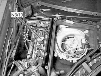
The main element of the system is the onboard processor, often called the electronic control module (ECM), or a power unit operation control module (RSM)
The ECM/PCM is the brain of the engine management system. The initial data is fed to the module from various information sensors and other electronic components (switches, relays, etc.). Based on the analysis of the data coming from the information sensors, and in accordance with the basic parameters stored in the processor memory, the ECM / PCM generates commands for the operation of various control relays and actuators, thereby adjusting the operating parameters of the engine, and ensuring maximum efficiency of its return at a minimum fuel consumption.
The OBD processor memory data is read using a special scanner connected to the diagnostic connector for reading the database (DLC) or using the auxiliary LED, as well as by the codes displayed on the automatic HF display.
Information about diagnostic tools
Checking the correct functioning of the components of the injection systems and reducing the toxicity of exhaust gases is carried out using a universal digital meter (multimeter)
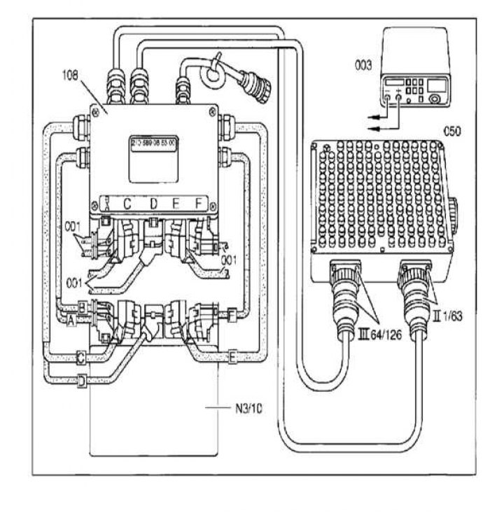
Connecting a multimeter to the connectors of the engine control unit using an auxiliary splitter
The use of a digital meter is preferred for several reasons. Firstly, it is quite difficult for analog devices to (sometimes impossible), to determine the result of the indication with an accuracy of hundredths and thousandths, while when examining circuits that include electronic components, such accuracy is of particular importance. The second, no less important, reason is the fact that the internal circuit of a digital multimeter has a fairly high impedance (the internal resistance of the device is 10 mΩ). Since the voltmeter is connected in parallel to the circuit under test, the measurement accuracy is higher, the smaller the current will pass through the device itself. This factor is not significant when measuring relatively high voltage values (9÷12 V), however, it becomes decisive in the diagnosis of elements that produce low-voltage signals, such as, for example, a λ-probe, where it is a matter of measuring fractions of a volt.
Parallel monitoring of signal parameters, resistances and voltages in all control circuits is possible using a splitter connected in series to the engine control unit connector. At the same time, with the engine turned off, running or while the car is moving, the parameters of the signals at the splitter terminals are measured, from which a conclusion is made about possible defects.
To diagnose electronic systems of the engine, automatic transmission, ABS, SRS and others, special diagnostic scanners or testers with a specific cartridge can be used (if provided), universal cable and connector. In addition, for this purpose, you can use an expensive specialized automotive diagnostic computer, specially designed for the complete diagnosis of most systems of modern cars (e.g. ADC2000 from Launch HiTech). Also, for this purpose, you can use scanners and specialized diagnostic analyzers, such as FDS 2000, Bosch FSA 560, KTS500 (0 684 400 500) or a regular personal computer with a special adapter, cable (e.g. kit 1 687 001 439) and installed by the program browser OBD II.
Some scanners, in addition to the usual diagnostic operations, allow, when connected to a personal computer, to print circuit diagrams of electrical equipment stored in the memory of the control unit (if laid down), program the anti-theft system, observe the signals in the car circuits in real time.
It is necessary to carry out several checks on different diagnostic connectors. First of all, check the duty cycle of the pulse.
Diagnostics of electronic control systems for engine, injection and ignition, automatic air conditioning and ABS/ASR/ETS/ESP
Layout and design of diagnostic connectors
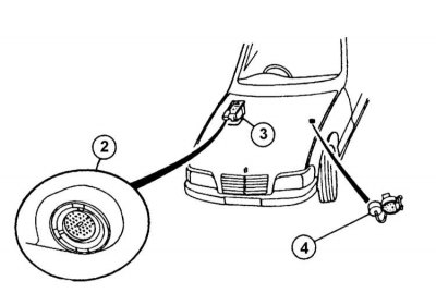
Location of diagnostic connectors
2 - 38-pin connector if installed
3 - Location of the connector
4 - 9-pin connector if installed
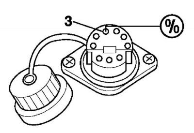
9-pin connector for diagnosing the control system by the value of the duty cycle of the pulse, using a device for measuring the so-called. the duration of the closed state of the breaker contacts (dwell-meter)
1 - Output TD switch; 2 - Housing; 3 - Diagnosis output; 4 - Conclusion 1 of the ignition coil; 5 - Conclusion 15 of the ignition coil; 6 - Conclusion +30; 7 and 9 - Conclusions to the TDC sensor; 8 - Screen
Pin assignment of the 38-pin diagnostic connector
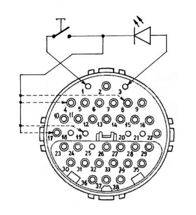
38-pin diagnostic connector for flashing codes
Connect the wires according to the diagram. The wire shown with a broken line is connected to a specific terminal for diagnosing a specific system (refer to the contact assignment list):
- To conclusion 4 - for diagnosing the injection system;
- To conclusion 8 - for diagnosing the main unit;
- To conclusion 17 - for diagnosing the ignition system;
- To conclusion 19 - to check the diagnostic unit.
The connector terminals have the following function:
| Output No | Purpose | |
| 1 | Weight, circuit 31 (W12, W15, electronics ground) | |
| 2 | Voltage, circuit 87 | |
| 3 | Voltage, circuit 30 | |
| 4 | EDS | Electronic injection system (diesel engines) |
| DFI | Fuel injection with electronic distribution (diesel engines) | |
| IFI | Sequential electronic fuel injection (diesel models) | |
| HFM-SFI | HFM Sequential Port Injection/Ignition System (engines 104) | |
| LH-SFI | LH sequential port injection system (engines 104, 119, 120 [right]) | |
| ME-SFI | ME sequential port injection system (engines 119, 120 [right]) | |
| 5 | LH-SFI | LH sequential port injection system (motors 120 [left]) |
| ME-SFI | ME sequential port injection system (motors 120 [left]) | |
| 6 | ABS | Anti-lock brake system |
| ETS | Electronic traction control | |
| ASR | Acceleration slip adjustment | |
| ESP | Electronic Stabilization Program | |
| 7 | EA | Electronic acceleration |
| CC/ISC | Speed Control/Idle Stabilization System | |
| 8 | VM | Basic module |
| BAS | brake assistant | |
| 9 | ASD | Automatic differential lock |
| 10 | ETC | Electronic transmission control (AT 722.6) |
| 11 | ADS | Adaptive cushioning system |
| 12 | SPS | Vehicle speed sensitive power steering system |
| 13 | TNA Signal (petrol models), LH-SFI engines | |
| TN signal (petrol models), HFM motors (ME) -SFI | ||
| 14 | Signal, duty cycle information, engines 119, 120 LH-SFI (rights.) | |
| 15 | Signal, duty cycle information, 120 LH-SFI motors (a lion.) | |
| IC | instrument cluster | |
| 16 | A/C | Air conditioning system |
| 17 | DI | Distributor ignition system, 104, 119 and 120 engines (rights.) |
| TD signal (temporary separation) (diesel models) | ||
| TN signal, LH-SFI motors | ||
| 18 | DI | Distributor ignition system, LH-SFI engines |
| 19 | DM | Diagnostic module |
| 20 | PSE | Pneumatic equipment |
| 21 | CF | Comfort |
| 23 | ATA | Anti-theft alarm |
| 24-27 | Not used | |
| 28 | PTS | Parktronic system |
| 29 | Not used | |
| 30 | AB | Airbags/Belt Pretensioners ETR (SRS) |
| 31 | RCL | Remote control of a single lock |
| 32-33 | Not used | |
| 34 | CNS | Communication and navigation system |
| 35-38 | Not used |
Location of the 16-pin diagnostic connector (on USA models)
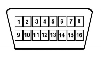
OBD 16-pin diagnostic connector terminal identification (on USA models)
The connector terminals have the following function:
| Output No | Purpose |
| 1 | — |
| 2 | — |
| 3 | TNA signal |
| 4 | Housing connection, terminal 31 |
| 5 | Housing - signal output, terminal 31 |
| 6 | CAN data bus high |
| 7 | Engine electronics (ME) |
| 8 | Nutrition, cl. 87 |
| 9 | Anti-slip system (ETS) |
| 10 | — |
| 11 | Transmission control unit (ETC) |
| 12 | activity module (AAM - All Activity Module) |
| 13 | Security systems |
| 14 | CAN Data Bus Low |
| 15 | IC dashboard |
| 16 | Plus batteries through the fuse. Under voltage in any position of the ignition switch, cl. thirty |
Pulse duty cycle measurement
1. First, measure the duty cycle of the pulses that characterize the operation of the mixture quality control system and its malfunctions, repeated during the last four engine starts. This will require a device for measuring the so-called. the duration of the closed state of the breaker contacts (dwell-meter), lambda probe tester or digital multimeter.
2. Connect the + terminal of the device to the 3rd pin of the 9-pin connector and the negative to the car body.
3. Start and warm up the engine to operating temperature.
4. Stop the engine and turn on the ignition again. Take the % reading of the device, and compare with the decoding below. After starting the engine, the instrument readings should change, otherwise there is a malfunction.
Reading and deleting flash codes
1. Reading codes is done using a simple circuit of a pushbutton switch and an LED. Depending on the type of diagnostic connector and the system being diagnosed, connect the circuit according to the illustration.

2. Turn on the ignition.
3. Press and hold the switch button for 2-4 sec (or 5-6 sec on models with Bosch ECM -8/93) and let her go. After 2 seconds, the LED will give a code, the value of which is equal to the number of flashes. Flash duration 0.5 sec, interval 1 sec. Identify the code by the decryption below. To read the next code, press the button again. To erase this code, press the button and hold it for 6-8 seconds. (or 8-9 sec on models with Bosch ECM -8/93). In addition, on some models, erasing codes in memory is possible by disconnecting the negative terminal of the battery.
4. Turn off the ignition and disconnect the circuit to check.
Personal computer interface controller with OBD II on-board self-diagnosis system according to SAE standards protocols (PWM and VPW) and ISO 9141-2
Attention! The controller is not intended to be connected to the first generation on-board self-diagnosis systems (OBD I)!
Note. The VPW standard is met by GM models, PWM by Ford, ISO 9141-2 by Asian and European models.
Total information
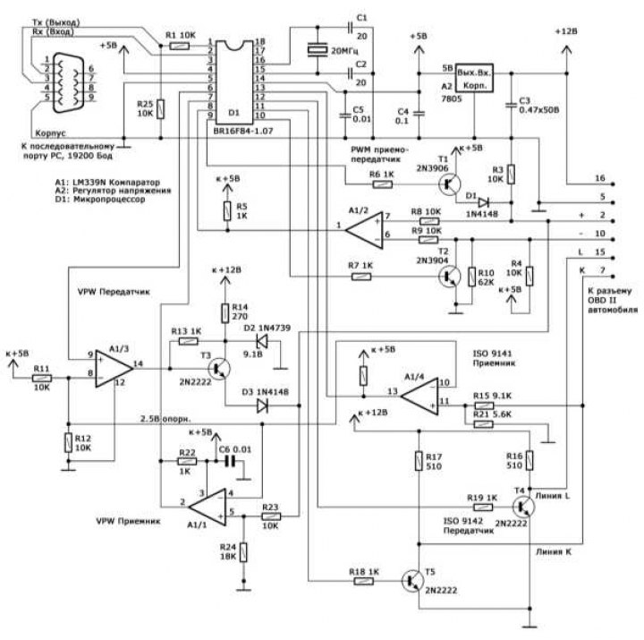
Scheme of the organization of the interface controller with the on-board self-diagnosis system OBD II
The device in question is a microcontroller made using CMOS technology (CMOS). The device plays the role of a simple scanner and is designed to read diagnostic codes and data from the OBD II system (engine speed, coolant and intake air temperature, load characteristics, air flow to the engine, etc.) within the scope of SAE J1979 standard via any type of bus (PWM, VPW and ISO 9141-2).
The main purpose
To connect to a computer, a 3-wire wire is sufficient, the connection to the diagnostic connector is carried out with a 6-wire wire. The power supply is supplied to the adapter via the 16-pin OBD diagnostic socket.
Recommendations for use
An unshielded cable, no longer than 1.2 m, can be used to connect the device to the car, which is of particular importance when using the PWM protocol. When using a longer cable, reduce the resistance of the resistors at the input of the device (R8 and R9 or R15). When using a shielded cable, the shield should be disabled to reduce capacitance.
The cable for connecting to the computer's serial port can also be unshielded. The device works stably with a cable length of up to 9 m. For significantly longer cable lengths, a more powerful RS 232 communicator should be used.
The topology of electrical connections is arbitrary. Use additional shunt capacitors for high humidity.
Free software (browser) for reading codes and data can be downloaded from the websites of manufacturers, or the website of our publishing house arus.spb.ru and is intended for use under DOS. Insignificant size of the software application in the variant «under DOS» allows you to fit it on a DOS boot floppy and use it even on computers equipped with non-DOS compatible software. An optional condition is even the presence of a hard disk in the computer.
General principles of data exchange
Note. Unless otherwise stated, all numbers are in hexadecimal format (hex).
Data exchange takes place over a three-wire serial connection without the use of initialization exchange of service messages (handshaking). The device listens to the channel for messages, executes the received commands and transmits the results to the personal computer (PC), then immediately returns to listening mode. The data entering and leaving the controller are organized as a chain of consecutive bytes, the first of which is the control one.
Typically, the control byte is a number from 0 to 15 dec (in decimal) (or 0-F hex), which describes the number of information bytes that follow. So, for example, a 3-byte command would look like this: 03 (control byte), 1st byte, 2nd byte, 3rd byte.
A similar format is used both for incoming commands to poll the on-board self-diagnosis system, and for outgoing messages containing the requested information.
It should be noted that only four low bits are used in the control byte - the high bits are reserved for some special commands and can be used by the PC when initializing the connection with the controller and negotiating the data transfer protocol, as well as the controller to control transmission errors. In particular, in the event of a transmission error, the controller sets the most significant bit (MSB) control byte per unit. On successful transmission, all four high-order bits are set to zero.
Note. There are individual exceptions to the rules for using the control byte.
Initialization of the controller and on-board self-diagnosis system
To start data exchange, the PC must establish a connection with the controller, then initialize the controller and the OBD II data channel.
Establishing a connection
After connecting the controller to the PC and the OBD diagnostic connector, it must be initialized in order to prevent «freezes», related to noise in the serial lines if they were connected before the controller was powered on. At the same time, a simple check of interface activity is performed. First of all, a one-byte signal 20 hex is sent, which is perceived by the controller as a command to establish a connection. In response, the controller instead of the control sends a single byte FF hex (255 dec) and enters the data reception standby mode. The PC can now proceed to initialize the data link.
Note. This case is one of the few when the controller does not use the control byte.
Initialization
At this stage, the protocol is initialized, according to which data will be exchanged, and in the case of the ISO protocol, the on-board system is initialized. Data is exchanged using one of three protocols: VPW (General Motors), PWM (Ford) and ISO 9141-02 (Asian/European manufacturers).
Note. There are many exceptions: for example, when polling certain models of Mazda cars, you can use «Ford» PWM protocol. Thus, if you encounter transmission problems, you should first try to use some other protocol.
The choice of protocol is made by transmitting a combination consisting of the control byte 41 hex and the byte immediately following it, which determines the type of protocol: 0 = VPW, 1 = PWM, 2 = ISO 9141. For example, the command 41 02 hex initializes the ISO 9141 protocol.
In response, the controller sends a control byte and a status byte. Setting the MSB of the control byte indicates a problem, and the status byte following it will contain the corresponding information. Upon successful initialization, a check byte 01 hex is sent, indicating that a verification status byte follows. In the case of VPW and PWM protocols, the verification byte is a simple echo of the protocol-defining byte (0 or 1, respectively), when initializing the ISO 9141 protocol, this will be a digital key returned by the onboard OBD processor and determining which of the two slightly different protocol versions will be used.
Note. The digital key has a purely informational purpose. It should be noted that the initialization of the VPW and PWM protocols is much faster, since it only requires the transfer of the relevant information to the controller.
On models that meet the ISO standard, initialization takes about 5 seconds, spent on the information exchange of the adapter with the onboard processor, performed at a speed of 5 baud.
It should be noted to the reader that on some ISO 9141 family vehicles the protocol initialization is suspended if a data request is not sent within a 5 second interval - this means that the PC should automatically issue requests every few seconds, even at idle. mode.
After the connection is established and the protocol is initialized, regular data exchange begins, consisting of requests received from the PC and responses issued by the adapter.
Data exchange procedure
Controller operation when using protocols of the ISO 9141-2 and SAE family (VPW and PWM) occurs under several different scenarios.
Exchange via SAE protocols (VPW and PWM)
When exchanging data using these protocols, only one data frame is buffered, which means that it is necessary to specify the frame to be captured or returned. In some (rare) cases, the onboard processor may transmit packets consisting of more than one frame. In such a situation, the request must be repeated until all frames of the packet have been received.
The request is always formed as follows: [Control byte], [Request according to the SAE standard], [Frame number]. As mentioned above, the control byte is usually a number equal to the total number of bytes that follow it. The request is made in accordance with the SAE J1950 and J1979 specifications and consists of a header (3 bytes), sequences of information bytes and error control byte (CRC). Note that while information on request is generated in strict accordance with SAE specifications, the consumer of the control byte and frame number is the interface controller.
Upon successful completion of the procedure, the response message always has the following format: [Check Byte], [SAE Standard Response]. The control byte, as before, determines the number of information bytes following it. The response, in accordance with the requirements of the SAE standard, consists of a header (3 bytes), strings of information bytes and a CRC byte.
On failure, a 2-byte response message is sent: [Control byte], [Status byte]. In this case, the MSB is set in the control byte. The four least significant bits form the number 001, indicating that the control is followed by a single byte, the status byte. This situation can occur quite often, because Specifications allow the possibility of the on-board processor not issuing data, as well as the transmission of incorrect data in the case when the request does not meet the standard supported by the vehicle manufacturers. It is also possible that the requested data is not available in the processor's RAM at the current time. When the controller does not receive the expected response, or receives corrupted data, the MSB of the control byte is set, and the status byte is issued after the control.
For bus collisions, the interface generates a single 40 hex byte, which is the control byte with the least significant bit set to zero. A similar situation can occur quite often when the car bus is loaded with messages of a higher priority than the diagnostic data - the computing device must repeat the original request.
Exchange according to ISO 9141-2 protocols
The ISO 9141-2 standard is used by most Asian and European automotive manufacturers. The structure of the generated PC request is not much different from that used in the SAE standards, with the only difference that the adapter does not need information about the frame number and the corresponding data should not be present in the packet. Thus, a request always consists of a check byte followed by a string of information bytes, including the checksum. As a response message, the controller simply relays the signals generated by the onboard processor. There is no check byte in the response message, so the PC accepts the incoming information as a continuous stream until the chain is interrupted by a pause of 55 milliseconds, indicating the completion of the information packet. Thus, the response message may consist of one or more frames in accordance with the requirements of the SAE J1979 specifications. The controller does not analyze frames, discard non-diagnostic frames, etc. The PC must process the incoming data on its own in order to isolate individual frames by analyzing the header bytes.
Note. Responses to most requests consist of a single frame.
Modifications of controllers of the latest versions
Note. All information bytes are transmitted in hexadecimal format (hex).
Note. The character XX means an undefined, reserved, or unrecognized byte.
Below are the main differences in the process of data transfer using the SAE and ISO 9141 protocols, which are typical for the latest interface controllers, as well as the procedure for transferring data using the ISO 14230 protocol:
- 1) ISO 9141: Address byte added;
- 2) ISO 9141: Not one, but both key bytes are returned; (extra byte is also returned in SAE modes, however it is not used here).
- 3) Added support for ISO 14230 protocol.
Establishing a connection
The connection setup order has not changed:
| Shipping: | 20 |
| Reception: | FF |
Protocol selection
The protocol is selected as follows:
| VPW: | |
Shipping: | 41, 00 |
Reception: | 02, 01, XX |
PWM: | |
Shipping: | 41, 01 |
Reception: | 02, 01, XX |
ISO 9141: | |
Shipping: | 42, 02, adr, where: adr - address byte (usually 33 hex) |
Reception: | 02, K1, K2, where K1, K2 are ISO key bytes Or: 82, XX, XX (ISO 9141 initialization error) |
ISO 14230 (fast initialization): | |
Shipping: | 46, 03, R1, R2, R3, R4, R5, where: R1 ÷ R5 - message about the start of an ISO 14230 connection request, usually R1 ÷ R5 = C1, 33, F1, 81, 66 |
Reception: | S1, S2, ………, where S1, S2, ……… is the message about the start of the ISO 14230 response to establish a connection |
Note. More than one ECU may be transmitted in series. A negative response code can be used as a response.
A typical positive response looks like this:
S1, S2, ……. = 83, F1, 10, C1, E9, 8F, BD ISO 14230 (slow initialization): | Similar to ISO 9141 |
Remark and comments
If you plan to use the controller to transfer data only through any one or two of the protocols, unnecessary components can be excluded.
For example, when organizing a scheme for the VPW protocol (GM) only three wires of electrical wiring are required in the wire connecting the controller to the car (terminals 16, 5 and 2).
If the PWM protocol is not used, the elements R4, R6, R7, R8, R9, R10, T1, T2 and D1 may be excluded.
In case of refusal to exchange under the ISO protocol, the following elements are subject to exclusion: R15, R16, R17, R18, R19, R21, T4 and T5.
Rejection of the use of the VPW protocol allows you to exclude the following elements: R13, R14, R23, R24, D2, D3 and T3.
Carbon film resistors with 5% resistance tolerance are used.
Note the absence of an emergency reset button (RESET), - if necessary, such a reboot can be done by disconnecting the controller from the car connector (the interface processor will restart automatically). Restarting the software on the PC will re-initialize the interface.