



Contents: General information ↡ Main purpose ↡ Recommendations for use ↡ General principles of data exchange ↡ Initialization of the controller and…↡ Establishing a connection ↡ Initialization ↡ Data exchange procedure ↡ Exchange via SAE protocols (VPW and…↡ Exchange according to ISO 9141-2…↡ Modifications made to the latest…↡ Establishing a connection ↡ Note and comments ↡
Controller for interfacing a personal computer with the on-board OBD II self-diagnostic system according to SAE (PWM and VPW) and ISO 9141-2 standard protocols.
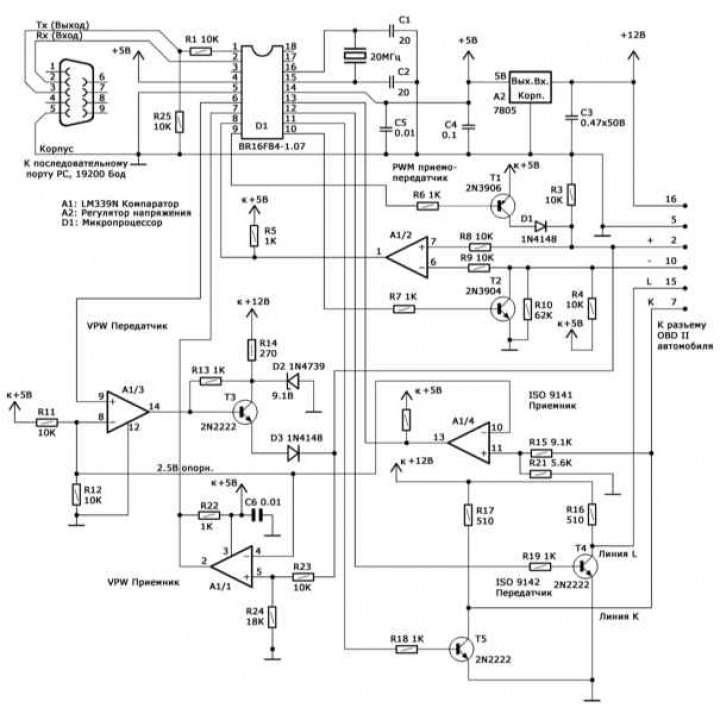
Scheme of controller for interfacing personal computer with on-board self-diagnostic system OBD II
Note: GM models comply with the VPW standard, Ford models comply with the PWM standard, and Asian and European models comply with the ISO 9141-2 standard.
General information
The device under consideration is a microcontroller made using CMOS technology.
Attention! The controller is not intended for connection to first-generation on-board self-diagnostic systems (OBD I)!
The device acts as a simple scanner and is designed to read diagnostic codes and OBD II system data (engine speed, coolant and intake air temperature, load characteristics, air flow rate entering the engine, etc.) within the framework of the SAE J1979 standard via any type of bus (PWM, VPW and ISO 9141-2).
Main purpose
A 3-wire cable is sufficient for connection to the computer, and a 6-wire cable is used to connect to the diagnostic connector. Power is supplied to the controller via the 16-pin OBD diagnostic connector. The schematic diagram of the controller is shown in the illustration.
Recommendations for use
To connect the device to the car, an unshielded cable of no more than 1.2 m in length can be used, which is especially important when using the PWM protocol. When using a longer cable, the resistance of the resistors at the input of the device should be reduced (R8 and R9 or R15). When using a shielded cable, the shield should be disconnected to reduce capacitance.
The cable for connecting to the computer's serial port can also be unshielded. The device works stably with a cable up to 9 m long. With a significantly longer cable, a more powerful RS 232 communicator should be used.
The topology of electrical connections is arbitrary. In case of high humidity, use additional shunt capacitors.
Free software (browser) for reading codes and data can be downloaded from manufacturers' websites and is intended for use under DOS. The small size of the software application in the "under DOS" version allows it to be placed on a DOS boot diskette and used even on computers equipped with DOS-incompatible software. Even the presence of a hard disk in the computer is not a mandatory requirement.
General principles of data exchange
Note: Unless otherwise noted, all numbers are in hex format.
The decimal format is indicated by the dec label.
Data exchange occurs via a three-wire serial connection, without the use of initialization exchange of service messages (handshaking). The device listens to the channel for messages, executes the received commands and transmits the results to the personal computer (PC), after which it immediately returns to the listening mode. The data entering and leaving the controller is organized as a chain of sequential bytes, the first of which is the control byte. Usually the control byte is a number from 0 to 15 dec (or 0-F hex), which describes the number of information bytes that follow. For example, a 3-byte command would look like this: 03 (control byte), 1st byte, 2nd byte, 3rd byte. This format is used both for incoming commands to poll the on-board self-diagnostics system and for outgoing messages containing the requested information. It should be noted that only four low-order bits are used in the control byte - the high-order bits are reserved for some special commands and can be used by the PC when initializing the connection with the controller and agreeing on the data transfer protocol, as well as by the controller to monitor transmission errors. In particular, in the event of a transmission error, the controller sets the most significant bit (MSB) of the control byte to one. If the transmission is successful, all four high-order bits are set to zero.
Note: There are some exceptions to the rules for using the control byte.
Initialization of the controller and on-board self-diagnostic system
To start data exchange, the PC must establish a connection with the controller, then initialize the controller and the OBD II data channel.
Establishing a connection
After connecting the controller to the PC and the OBD diagnostic connector, it must be initialized to prevent "hangs" associated with noise in the serial lines if they were connected before the controller was powered on. At the same time, a simple check of the interface activity is performed. First, a single-byte signal 20 (hex) is sent, which the controller perceives as a command to establish a connection. In response, the controller sends a single byte FF hex (255 dec) instead of the control byte and goes into data reception standby mode. Now the PC can proceed to initializing the data channel.
Note: This is one of the few cases where the controller does not use a control byte.
Initialization
At this stage, the protocol by which data will be exchanged is initialized, and in the case of the ISO protocol, the on-board system is initialized. Data is exchanged using one of three protocols: VPW (General Motors), PWM (Ford) and ISO 9141-02 (asian/European manufacturers).
Note. There are many exceptions: for example, when polling some Mazda models, the Ford PWM protocol may be used. Therefore, if transmission problems occur, you should first try to use some other protocol. The protocol is selected by transmitting a combination consisting of the control byte 41 (hex) and the immediately following byte defining the protocol type: 0 = VPW, 1 = PWM, 2 = ISO 9141. For example, the command 41 (hex) 02 (hex) initializes the ISO 9141 protocol.
In response, the controller sends a control byte and a status byte. Setting the MSB of the control byte indicates that there are problems, and the following status byte will contain the corresponding information. If initialization is successful, a control byte of 01 (hex) is sent, indicating that a verification status byte follows. In the case of VPW and PWM protocols, the verification byte is a simple echo of the protocol selection byte (0 or 1, respectively), when initializing the ISO 9141 protocol, this will be a digital key returned by the on-board OBD processor and will determine which of the two slightly different protocol versions will be used.
Note. The digital key has a purely informational purpose. It should be noted that the initialization of the VPW and PWM protocols is much faster, since it only requires the transfer of the relevant information to the controller. On models that meet the ISO standard, initialization takes about 5 seconds, spent on the exchange of information between the controller and the on-board processor, performed at a speed of 5 baud. The reader should note that on some models of cars of the ISO 9141 family, protocol initialization is suspended if a request for data output is not transmitted within a 5-second interval - this means that the PC must automatically issue requests every few seconds, even in idle mode.
After the connection is established and the protocol is initialized, the regular data exchange begins, consisting of requests received from the PC and responses issued by the controller.
Data exchange procedure
The controller operates in slightly different scenarios when using the ISO 9141-2 and SAE (VPW and PWM) protocols.
Exchange via SAE protocols (VPW and PWM)
When exchanging data using these protocols, only one data frame is buffered, which means that the frame to be captured or returned must be specified. In some (rare) cases, the onboard processor may transmit packets consisting of more than one frame. In such a situation, the request must be repeated until all frames in the packet have been received.
The request is always formed as follows: [Control Byte], [SAE Standard Request], [Frame Number]. As mentioned above, the control byte is usually a number equal to the total number of bytes that follow it. The request is formed in accordance with the SAE J1950 and J1979 Specifications and consists of a header (3 bytes), a sequence of data bytes, and an error check byte (CRC). Note that while the request information is formed in strict accordance with the SAE Specifications, the consumer of the control byte and frame number is the interface chip.
If the procedure is successfully completed, the response message always has the following format: [Control byte], [SAE standard response]. The control byte, as before, determines the number of information bytes that follow it. The response, in accordance with the SAE standard, consists of a header (3 bytes), a chain of information bytes, and a CRC byte.
In case of failure, a 2-byte response message is sent: [Control byte], [Status byte]. In this case, the MSB is set in the control byte. The four least significant bits form the number 001, indicating that the control byte is followed by a single byte, the status byte. This situation can occur quite often, since the Specifications allow for the possibility of the on-board processor not issuing data, as well as the transmission of incorrect data in the event that the request does not correspond to the standard supported by the vehicle manufacturers. A situation is also possible when the requested data is not present in the processor's RAM at the current time. When the chip does not receive the expected response, or receives corrupted data, the MSB of the control byte is set, and the status byte is issued after the control byte.
In case of collisions in the bus, the interface generates a single byte 40 (hex), which is a control byte with the least significant bit set to zero. Such a situation can occur quite often when loading the car bus with messages of higher priority than diagnostic data - the computing device must repeat the original request.
Exchange according to ISO 9141-2 protocols
The ISO 9141-2 standard is used by most Asian and European automotive manufacturers. The structure of the request generated by the PC is not much different from that used in the SAE standards, with the only difference being that the chip does not need information about the frame number and the corresponding information should not be present in the packet. Thus, the request always consists of a control byte followed by a chain of information bytes, including a checksum. As a response message, the chip simply retransmits the signals generated by the on-board processor. There is no control byte in the response message, so the PC receives incoming information continuously until the chain is interrupted by a 55-millisecond pause indicating the end of the information packet. Thus, the response message may consist of one or more frames in accordance with the requirements of the SAE J1979 Specifications. The chip does not analyze frames, does not discard non-diagnostic frames, etc. The PC must independently process the incoming data in order to isolate individual frames by analyzing the header bytes.
Note: Responses to most queries consist of a single frame.
Modifications made to the latest versions of interface controllers
Below are the main differences in the data transfer process using the SAE and ISO 9141 protocols, typical for the latest versions of interface controllers, as well as the procedure for data transfer using the ISO 14230 protocol:
- 1) ISO 9141 Standard: Added Address Byte;
- 2) ISO 9141 standard: Not one, but both key bytes are returned; (the extra byte is also returned in SAE modes, but is not used here).
- 3) Added support for ISO 14230 protocol.
Note: All data bytes are transmitted in hexadecimal format.
The XX symbol denotes an undefined, reserved, or unrecognized byte.
Establishing a connection
The connection setup procedure has not changed:
- Dispatch: 20
- Reception: FF
Selecting a protocol
VPW:
- Dispatch: 41, 00
- Reception: 02, 01, XX
PWM:
- Dispatch: 41, 01
- Reception: 02, 01, XX
ISO 9141:
- Sending: 42, 02, adr, where: adr is the address byte (usually 33 hex)
- Receive: 02, K1, K2, where K1, K2 are ISO key bytes
- Or: 82, XX, XX (iSO 9141 initialization error)
ISO 14230 (fast initialization):
- Sending: 46, 03, R1, R2, R3, R4, R5, where: R1÷R5 - ISO 14230 connection setup request start message, usually R1÷R5 = C1, 33, F1, 81, 66
- Receive: S1, S2, ………, where S1, S2, ……… is the ISO 14230 connection setup response start message
Note: More than one ECU may be transmitted in succession. A negative response code may be used as a response.
A typical positive answer looks like this: S1, S2, ……. = 83, F1, 10, C1, E9, 8F, BD
ISO 14230 (slow initialization): Similar to ISO 9141.
Note and comments
If the controller is planned to be used for data transmission only by one or two of the protocols, unnecessary components can be excluded. For example, when organizing the circuit for the VPW (GM) protocol, only three wires of electrical wiring will be required in the controller connection wire to the car (terminals 16, 5 and 2).
If the PWM protocol is not used, elements R4, R6, R7, R8, R9, R10, T1, T2 and D1 can be excluded.
When refusing to exchange via the ISO protocol, the following elements are subject to exclusion: R15, R16, R17, R18, R19, R21, T4 and T5.
By not using the VPW protocol, the following elements can be eliminated: R13, R14, R23, R24, D2, D3 and T3.
Carbon film resistors with 5% resistance tolerance are used.
Please note that there is no emergency reset button (RESET), if necessary, such a reset can be done by disconnecting the controller from the car connector (the interface processor will reboot automatically). Restarting the software on the PC results in a new initialization of the interface.