



Contents: Features of the ABS, ESP and BAS…↡ Pressure and return pump (A7/3m1) ↡ Solenoid valves for maintaining and…↡ Low pressure tank (11) ↡ Control solenoid valves of circuits…↡ Suction solenoid valves (A7/3y22 and…↡ Brake pressure sensors (B34, B34/1,…↡ Reducing background noise ↡ Steering angle and body acceleration…↡ Operating principle of the sensor ↡
Hydraulic elements of the brake and auxiliary systems BAS and ESP
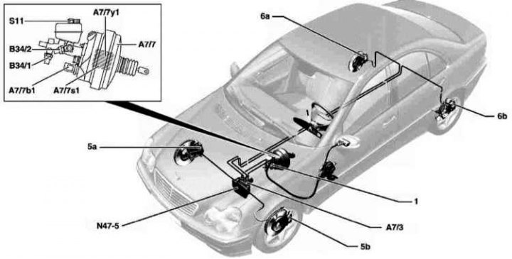
1 - Dual-circuit GTZ; 5a - Right front wheel brake caliper; 5b - Left front wheel brake support; 6a - Right rear wheel brake support; 6b - Left rear wheel brake support; A7/7 - Brake Assist (BAS); b1 - BAS diaphragm stroke sensor; s1 - BAS release switch sensor; y1 - BAS electromagnetic valve; N47-5 - ESP/BAS control unit; S11 - Brake fluid level switch
Schematic diagram of the hydraulic circuit of the ESP anti-skid system
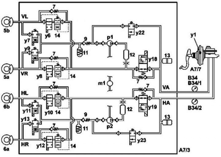
7 - Check valve; 9 - One-way check valve of the return pump; 11 - Low pressure accumulator; 12 - Damper with control plate; 13 - Pulsation damper diaphragm; 14 - Barosensitive control plate; A7/3 - Hydraulic modulator of auxiliary brake systems; m1 - Pressure and return pump; p1 - Self-priming front circuit pump; p2 - Self-priming rear circuit pump; y6 - Left front solenoid valve, pressure maintenance; y7 - Left front solenoid valve, pressure relief; y8 - Right front solenoid valve, pressure maintenance; y9 - Right front solenoid valve, pressure relief; y10 - Left rear solenoid valve, pressure maintenance; y11 - Left rear solenoid valve, pressure relief; y12 - Right rear solenoid valve, pressure maintenance; y13 - Right rear solenoid valve, pressure relief; y18 - Front circuit control solenoid valve; y19 - Rear circuit control solenoid valve; y22 - Front circuit suction solenoid valve; y23 - Suction solenoid valve rear circuit; B34 - ESP brake pressure sensor (models, produced since 08/01); B34/1 - ESP pressure sensor 1 (not installed on 08/01 models); B34/2 - ESP pressure sensor 2 (not installed on 08/01 models); VA - Front Axle Contour; HA - Rear Axle Contour; VL - Front left wheel brake; VR - Front right wheel brake; HL - Rear left wheel brake; HR - Rear right wheel brake
Electrical controls for the brake and auxiliary systems BAS and ESP
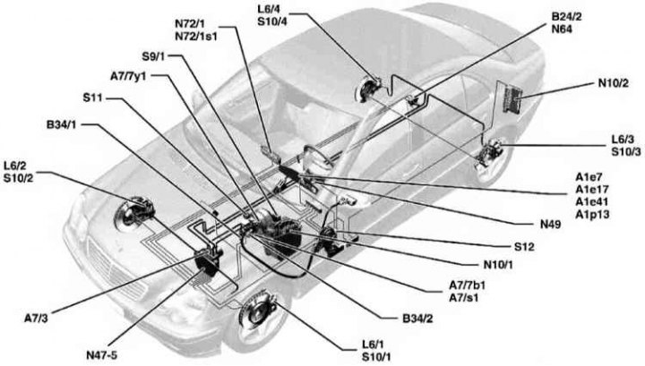
A1 - Instrument panel; e7 - Brake fluid level and parking brake engagement indicator light; e17 - ABS warning light; e41 - ESP warning light; p13 - Multifunctional display; A7/3 - Hydraulic modulator of auxiliary brake systems; A7/7 - Brake Assist (BAS); b1 - BAS diaphragm stroke sensor; s1 - BAS release switch sensor; y1 - BAS electromagnetic valve; B24/2 - Lateral overload sensor; B34/1 - ESP brake pressure sensor 1; B34/2 - ESP brake pressure sensor 2; L6/1 - Left front wheel speed sensor; L6/2 - Right front wheel speed sensor; L6/3 - Left rear wheel speed sensor; L6/4 - Right rear wheel speed sensor; N10/1 - Front SAM control unit with fuse and relay box; N10/2 - SAM control unit with rear fuse and relay box; N47-5 - ESP/BAS control unit; N49 - Steering angle sensor; N64 - Yaw Rate Sensor; N72/1 - Upper control panel control unit; s1 - ESP OFF switch sensor; S9/1 - Brake light switch sensor; S10/1 - Left front brake shoe contact sensor; S10/2 - Right front brake shoe contact sensor; S10/3 - Left rear brake shoe contact sensor; S10/4 - Right rear brake shoe contact sensor; S11 - Brake fluid level switch; S12 - Parking brake arming switch
Design of the capacitive rotation and acceleration sensor of the ESP system
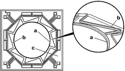
a - Silicon ring; b - Spring jumper; c - Electronic sensor
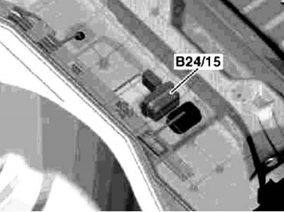
Location of the ESP anti-skid system body acceleration and rotation sensor
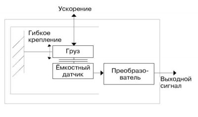
Functioning of the capacitive steering angle and acceleration sensor of the ESP system
The hydraulic brake system consists of a master brake cylinder, a brake booster, an ABS unit, and disc brakes on the front and rear wheels. The hydraulic brake system is divided into two circuits. One circuit acts on the front brakes, the second circuit on the rear wheels. If one of the circuits fails, for example, due to a fluid leak, the car is braked by the other circuit. The fluid pressure in both circuits is created by a dual master brake cylinder, which operates from the brake pedal.
The brake fluid reservoir is located in the engine compartment, on the driver's side, under the cover above the master brake cylinder. It supplies the entire system with brake fluid. The volume of fluid in the reservoir must be constantly monitored.
Description of the operation of the anti-lock brake systems ABS, Brake Assistance System BAS and Electronic Stability Program (anti-skid system) provided in the section "Controls and safe operation techniques".
The front brakes have a floating caliper. This design requires only one piston to operate both brake pads. The rear brakes have a fixed caliper.
The brake booster accumulates part of the vacuum created in the engine's intake manifold. Since a diesel engine lacks the necessary vacuum at the intake manifold, diesel-powered vehicles have a special vacuum pump mounted at the front, on the cylinder head, and driven by the camshaft.
By means of a suitable valve, the force from the brake pedal is increased by the action of vacuum.
The foot parking brake acts via cables on the rear wheel brakes. The rear wheels are additionally equipped with drum brakes built into the disc brakes. The drum brakes are activated only by the parking brake pedal. The rear wheel brake shoes are set automatically, which requires only in rare cases the parking brake to be adjusted, for example after repairs.
Features of the ABS, ESP and BAS auxiliary systems
Functioning of the hydraulic circuit of auxiliary brake systems
The hydraulic modulator of auxiliary brake systems (A7/3) includes components of the closed-loop dynamic control systems ABS, ASR and ESP.
Pressure and return pump (A7/3m1)
The self-priming pressure and return pumps (p1, p2) are integrated into the hydraulic modulator assembly (A7/3) and are switched by pulse signals during the pressure build-up and pressure release phases of the ASR and ESP active control systems, as well as during return flow adjustment when ABS is activated.
Solenoid valves for maintaining and relieving pressure (A7/3y6-y13)
One 2/2-way valve is used to control the pressure in the circuits of each wheel in the build-up/hold and hold/release phases of the ABS, ASR and ESP control modes.
Low pressure tank (11)
The low-pressure reservoir (11) is filled with brake fluid during the ABS, ASR or ESP pressure release phase and ensures its transfer to the pressure-return pump (p1/p2).
Control solenoid valves of circuits (A7/3y18 and y19)
The electromagnetic switch valves (y18 and y19) ensure the cut-off of the active pressure circuits of the front and rear axles from the brake master cylinder during the operation of ASR and ESP. The valves also ensure the pressure release when it rises above 150 atm. The brake fluid passed through the switch valves is directed back to the brake master cylinder.
Suction solenoid valves (A7/3y22 and y23)
The inlet solenoid valves (y22, y23) open during the ASR/ESP pressure build-up phases.
Brake pressure sensors (B34, B34/1, B34/2)
ESP Mk20 (models before 7/01) equipped with two brake pressure sensors. Sensor 1 (B34/1) monitors the pressure in the front brake circuit, sensor 2 (B34/2) - in the rear.
In ESP Mk25 (models from 8/01) only one sensor (B34) is used, monitoring the pressure in the front circuit.
The information provided by the sensors is transmitted to the control unit and is used to calculate the parameters of the closed control loop.
Reducing background noise
Self-starting pressure and return pumps (p1, p2) are started as needed to minimize noise levels.
Various damping components (13, 14) provide further noise damping. Each brake circuit is equipped with a separate damper (12), which reduces the noise level produced by the pump.
Steering angle and body acceleration sensor
The sensors monitoring angular velocities and lateral overloads are combined into a steering steepness and lateral overload assembly (B24/5), which allows saving the space they occupy. The micromechanical sensor assembly converts the lateral and vertical projections of angular accelerations into electrical signals. Elements of different masses under the influence of those arising during the non-inertial movement of the vehicle (making turns and accelerations) overloads provide varying degrees of deformation. A special electronic converter converts the received signals and transmits them via the CAN bus to the control unit of the anti-slip and anti-skid systems (N47).
Operating principle of the sensor
The sensor's sensitive element is formed from a micromechanical ring (a) equipped with eight spring bridges (b) that provide its movement and electromagnetic action. When rotating in the assembly, additional Coriolis forces arise, proportional to the rotation speed, recorded electromagnetically and after conversion in the ACIS module into the form of analog signals, sent to the control unit of the instrument panel.
The transverse overload measurement principle is based on the use of a spring-mass element with a capacitive detector. The operating voltage is supplied from the ESP control unit (N47-5).
The transverse loads that arise during cornering ensure the displacement of the spring-mass element from the equilibrium position by an amount proportional to the value of the resulting overload. Any change in the position of the element leads to a change in the detector capacity. The recorded deviation is then converted into a signal voltage, allowing the ESP control unit (N47-5) to make a quantitative assessment of the values of the recorded transverse overloads.
The electronic control unit ensures that the system, if damaged, (for example, a cable break), or when the voltage drops, it switches off automatically. The situation is displayed on the instrument panel by the orange ABS indicator lamp lighting up. At the same time, the ESP and BAS systems are switched off simultaneously, which is indicated by the ESP indicator lighting up. The main braking system retains its functionality. During braking, the car behaves as if the ABS system is absent.
If, for example, the ESP indicator light comes on while driving, this indicates a malfunction of the brake booster or anti-skid system. BAS and ESP are switched off. The normal system remains functional.
If the red indicator light comes on while driving (symbol: challenge sign) braking system, you must stop immediately and find out the cause. The reasons may be insufficient brake fluid or the parking brake is cocked.
If the ABS warning light comes on while driving:
1. Stop the car, turn off the engine and start it again.
2. Check the battery voltage. If the voltage is less than 10.5 V, charge the battery.
Caution! If the ABS warning light comes on when you start driving and then goes out after a while, this indicates low battery voltage, which increases after the generator starts working.
3. Check that the battery terminals are securely fastened.
4. Put the car on stands, remove the wheels and check the electrical wires leading to the wheel speed sensors for external damage. Other checks must be performed at a service station. The electronics have self-diagnostics, existing faults are registered by the system automatically. Checking the records and troubleshooting are performed at a service station.
Attention! Before performing electric welding work, it is necessary to disconnect the ABS connector. The connection is located in the engine compartment, at the top, on the driver's side, behind the removable cover. The connection is disconnected only when the ignition is off. When performing paintwork, do not heat the control unit to a temperature above +90°C.
When cleaning the brake system, dust is released that can be harmful to human health, so you should not inhale brake dust.
Working with the brake system requires special cleanliness and strict adherence to instructions. If you do not have the necessary experience, it is advisable to contact a service station.
Note: When driving on wet roads, it is necessary to periodically press the brake pedal to remove moisture from the brake discs.
As the wheel rotates, moisture is thrown off the brake discs by centrifugal force, but a film of silicone, rubber abrasion products, grease and other contaminants remain, reducing the effectiveness of the brakes.
After installing new brake pads, the latter must be worked in. Therefore, for the first 200 km of running, you should not brake hard unless necessary.
Corroded disc brakes create a shaking effect when braking, which does not disappear over time. In this case, it is necessary to replace the brake discs.
Dirt burning onto the surface of the brake pads and rain grooves cause grooves to form on the surface of the brake discs, which results in reduced braking efficiency.