



Schematic diagram of the injection system with exhaust gas recirculation
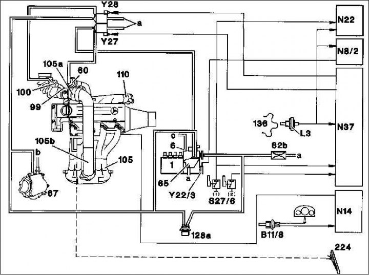
1. High pressure fuel pump; 6. Vacuum ignition timing regulator membrane mechanism retainer; 60. Exhaust gas recirculation valve; 62b. Choke with filter; 65. Vacuum relief valve; 67. Vacuum pump; 99. Hydraulic valve; 100. Hydraulic valve of the membrane mechanism of the vacuum regulator of ignition advance; 105. Intake gas line; 105a. Hydraulic valve body; 105b. Intake air connecting pipe 110. Exhaust manifold; 128a. Thermostat (closes at 30°C); 136. Flywheel; 224. Accelerator pedal; B11/8. Dual temperature sensor (cooling liquid/ preheating device); L3. Speed sensor; N14. Control relay; N₂2. Regulating device of the refrigeration unit compressor shutdown circuit; N37. ARF control unit; S27/6. micro switch; Y27. ARF changeover valve; Y28. Hydraulic valve changeover valve
2.0 l engine: the injectors are supplied by a Bosch in-line high-pressure fuel pump with a mechanical regulator and a built-in anti-shock circuit (KARA), which significantly reduces torsional vibrations in the drive phase.
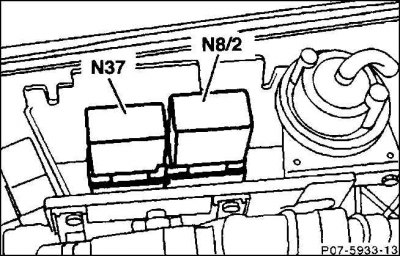
The control unit for the anti-shock circuit (N8/2), like the control unit for the exhaust gas recirculation (EGR), is located in the engine compartment on the right behind the front wall of the cab under the cover for the control units.
2.2/2.5 l engine: Electronic Diesel Control (EDC) enables the injection quantity to be matched more precisely to the vehicle's operating conditions, resulting in significant improvements in almost all operating conditions compared to mechanical systems.
2.2-litre engine: Mercedes is introducing a variable electronic fuel injection system with a distributor high-pressure fuel pump (EPIC = Electronic Programmable Injection Control) for the first time. Unlike an in-line high-pressure fuel pump, which has a plunger pair for each cylinder, the distributor high-pressure fuel pump has only two pistons rotating in a rotor of the booster pump, whereby the regulation of the fuel injection quantity and the peak distribution (distribution of the start of the peak load at increasing engine speeds in the direction of "early injection") is carried out by means of a piston, hydraulically controlled by electromagnetic valves.
The valves are activated by an electronic control unit. The type and duration of the control pulses depend on factors registered by the sensing elements and processed in the control unit using sorted universal characteristics. These include, among others, the pressure in the intake manifold, the engine speed, and the temperature of the intake air, coolant and fuel.
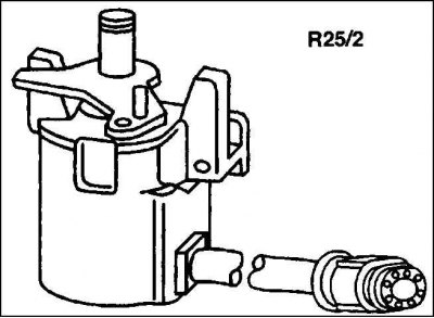
The position of the accelerator pedal is determined by a master device and switch (R25/2), the signals of which are precisely fed into the electronic control unit, where they are processed and monitored. The master device is located in the engine compartment on the left behind the front wall of the cabin and is connected to the accelerator pedal via a gas cable.
The engine operation is stopped by means of an electromagnetic valve. If its power supply is interrupted by itself from the ignition switch and the anti-theft system devices, or due to system errors in the control electronics, the valve shuts off the fuel supply to the pistons of the booster pump. If the shut-off valve fails, the control device sets the system of the amount of fuel injected to "0" (zero feed) and, thanks to this, stops the engine. At the same time, the malfunction is stored in the control device, and the EDS - control lamp - flashes on the instrument panel.
Additionally, with the activation of the electromagnetic valves in the exhaust gas recirculation (AGR) distribution pump in combination with the intake air throttling (ALD) system, it is regulated by means of the engine control valve, whereby the AGR valve and the throttle valve are respectively actuated by pneumatic actuators.
2.5 l engine: The 5-cylinder engine also features electronically controlled fuel injection in combination with an in-line high-pressure fuel pump (M/RE).
Instead of a mechanical speed controller (2.0L engine) the electromagnetic actuator takes over the regulation of the injected amount of fuel in accordance with the position of the accelerator pedal. The position of the accelerator pedal is determined by the engine control unit, as with the 2.2-liter engine.
In addition to regulating the amount of fuel injected, the electronic engine management system also takes over regulation of exhaust gas recirculation (EGR) in combination with intake air throttling (ALD) depending on engine speed, load and temperature.
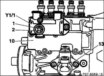
The engine is stopped by an electrohydraulic switch (Y1/1), which is located on the side of the high-pressure fuel pump. The fuel temperature sensor is also located in the same housing (contacts 1/2).
(Information copied from the website MercedesMan)
The fuel supply pump (13) is located outside the in-line fuel pump of the injectors. The coarse filter is located in the main filter housing, and heated fuel flows out of there, due to which it has better fluidity despite the low outside temperature.