
Underpressure control of the fuel supply system (engine 2.0)
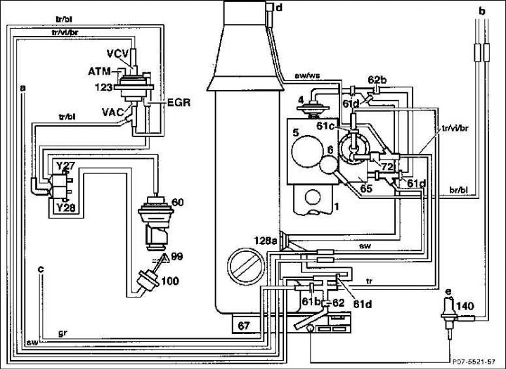
1. Fuel pump injectors; 4. PLA - box; PLA = Pneumatic Idle Speed Boost; 5. ADA - box; ADA = high pressure fuel pump rack travel limiter dependent on atmospheric pressure. Serves to correct low air densities at high altitudes; 6. Stopper of the membrane mechanism of the vacuum ignition timing regulator; 60. Exhaust gas recirculation valve; 61b. Throttle orange; 61c. Choke with a diameter of 0.5 mm, green; 61d. Connecting element yellow; 62b. Filter; 62b. Ventilation filter with 0.13 mm throttle 65. Vacuum control valve; 67. Vacuum pump; 72. Vibration damper; 99. Hydro valve; 100. Hydraulic valve of the membrane mechanism of the vacuum ignition timing regulator; 128a. Thermostat (closed at 30°C); 140. Check valve for the brake booster; Y27. Switching valve of the exhaust gas recirculation system; Y28. Hydraulic valve changeover valve; a - Ventilation of the interior of the car; b - Switching off with a key; c - Other consumers; e - To brake booster
The injection start of the injector fuel pump is checked or adjusted accordingly if the engine is producing too little power or a new fuel pump has been installed.
There are two different test and adjustment methods that can be used in a workshop, depending on its equipment: a static method using a position sensor and a dynamic test method using a digital control device. The static method using a position encoder is described here. A position sensor is required to set the start of fuel delivery by the pump (position sensor).
After the static setting, the start of the pump delivery must be checked dynamically in the workshop, and therefore also in idling mode. For engines with a volume of 2.2 / 2.5 liters, only a dynamic check is provided, or, accordingly, the setting of the start of fuel supply by the pump.
Examination
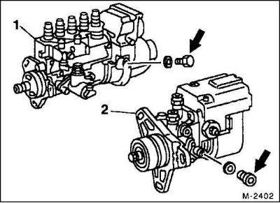
1 - In-line high pressure fuel pump
2 - High pressure distribution fuel pump
1. Remove the screw plug (arrow) on the side of the high pressure fuel pump.
Attention! If oil comes out, wipe it off with a rag.
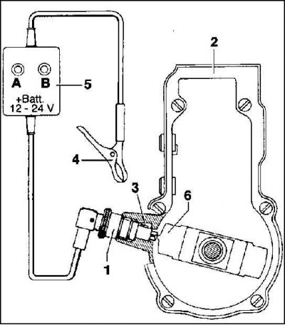
2. Install position sensor (1) in the regulator housing so that the guide pin (3) sensor pointing up. Tighten the union nut by hand.
3. Set the crankshaft to the position corresponding to the ignition moment of the first cylinder.
4. After that, turn the pulley further until the indicator sensor (5) light bulb will flash (A). Now keep turning the pulley quite slowly until both lights are on (A) And (IN).
In this case, both contacts of the position sensor (1), thanks to weight pins (6) centrifugal control mechanism are located on the mass, which is why both bulbs are lit. This is the position of the regulator (2) fuel pump injectors indirectly corresponds to the start of fuel supply by the pump.
5. The pulley should now be in position 14°+ 0.5°after TDC. That is, the original mark is above the position of the 14°mark on the pulley.
Attention! Do not rotate the motor in the opposite direction. If only a light bulb flashes (IN), then repeat the test. At the same time, turn the crankshaft about two turns and turn it especially slowly in the area where the light comes on.
Setting
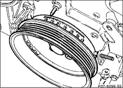
1. Set the crankshaft in the direction of rotation of the engine to 14°after the TDC of the first cylinder. To do this, first set the crankshaft to the position corresponding to the ignition moment, and then turn a little further.
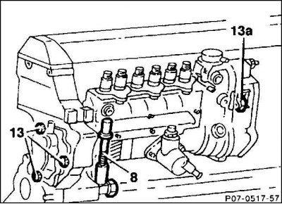
2. Loosen, without unscrewing, the bolts (13) on the flange of the high pressure fuel pump.
3. Loosen, without unscrewing, the bolts (13a) on the high pressure fuel pump support bracket.
4. Use a socket wrench to turn the tension bolt and thereby move the high pressure fuel pump until both lights on the indicator light come on (A) And (IN). In this case, turn the tension bolt to the right if, during the test, the start of pump delivery was located 14°after the TDC mark. If the pump should start flowing earlier, then turn the tension bolt to the left.
Attention! If it is not possible to move using the tension bolt, then it is necessary to remove and rearrange the injector pump (car workshop work).
5. With a torque of 25 Nm (indicative value) Tighten the injector pump mounting bolts on the flange and holder to failure.
6. Unscrew and remove the position sensor.
7. Screw in the screw plug with an aluminum O-ring to a torque of 30 Nm.
8. Check the gas system of rods and levers, adjust if necessary.
9. Check engine oil level, correct if possible.