
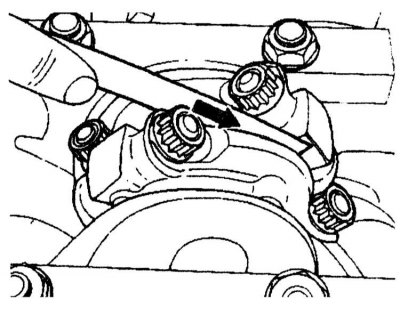
Oil pump installation details
1 - Oil pump; 6 - Bolt; 7 - Oil pump sprocket 8, 9 Bolt with gasket; 10 - Compensator; S43 - Oil level sensor
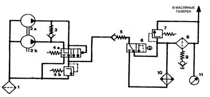
Pump and filter diagram
1 - Oil receiver and coarse filter of the oil pump; 2a - Tandem oil pump, first stage; 2b - Tandem oil pump, second stage; 3 - Pressure reducing valve; 4a - Pressure reducing valve; 4b - Oil pressure reducer; 5 - Anti-drainage valve; 6 - Thermostat; 7 - Oil filter bypass valve; 8 - Oil filter; 9 - Oil filter drain valve; 10 - Air oil cooler; 11 - Emergency oil pressure sensor
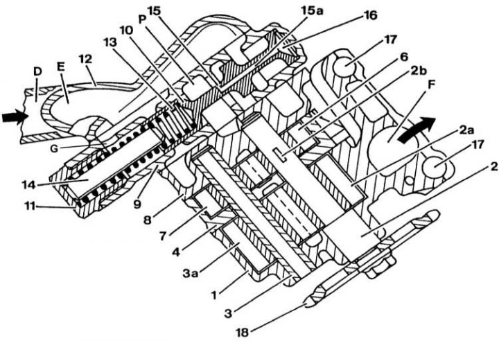
Construction of a two-stage oil pump
1 - Housing of the first stage of the oil pump; 2 - Roller drive of the first stage with pressed gear; 2a - Gear of the first stage; 3 - Pump shaft; 3a - Gear of the first stage; 4 - Housing of the second stage of the oil pump; 5 - Poppet valve; 6 - Second stage gear; 7 - Gear of the second stage; 8 - Guide cover; 9 - Pressure reducing valve body; 10 - Piston of the pressure reducing valve; 11 - Plug; 12 - Cover with oil receiver; 13 - Spring; 14 - Plunger; 15 - Bypass hole in the piston of the pressure reducing valve; 15a - Oil channel connecting with the working chamber; 16 - Working chamber; 17 - Hole for the pin; 18 - Drive sprocket; D - Suction oil; E - Suction chamber; F - Canal connecting to the main highway; P - Pressure chamber, primary oil flow; S - Pressure chamber, oil flow at the pump outlet; G - Pressure reducing valve opening