



Contents: Convergence ↡ Camber and lateral inclination of…↡ Longitudinal tilt of kingpin back ↡ Prerequisites for verification ↡ Checking/setting positive front…↡
Optimal driving characteristics and minimal tire wear are only achieved if the wheels are correctly aligned. In case of increased and uneven tire wear, as well as poor road holding – poor directional stability and insufficient cornering stability – you should contact a workshop to have the wheel alignment adjusted using optical methods.
Wheel alignment cannot be performed without the appropriate equipment. Therefore, only the basic concepts necessary for wheel alignment are described here.
Convergence
Toe-in is the angle at which the plane of the wheel deviates from the longitudinal axis of the car. Positive toe-in means that the wheels, when measured at their center height, are slightly closer together at the front than at the rear. Negative toe-in means that the wheels are more apart at the front than at the rear.
The Mercedes has both front and rear wheels with positive toe-in: front wheels – 0°25' (sports suspension 0°10'), rear wheels – 0°25'.
Camber and lateral inclination of the steering knuckle
Original article is on the portal mercedesman
Front axle
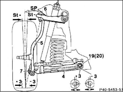
St – camber; Sp – transverse inclination of kingpin; 4 – lower suspension arm; 5 – steering knuckle 6 – upper suspension arm; 7 – knuckle joint; 19, 20 – bolts with eccentric; +/-3 – installation stroke – 3 mm
The camber and lateral inclination of the steering knuckle reduce the transfer of shocks to the steering and ensure minimal friction when cornering.
Camber is the angle by which the plane of the wheel deviates from the vertical. The front wheels, therefore, are further apart at the point of contact with the road than at the top with negative camber. The front and rear wheels of a Mercedes have negative camber.
The transverse inclination of the kingpin is the angle between the axis of rotation of the knuckle and the vertical at the point where the wheel is standing, when looking in the longitudinal direction of the car.
The camber and the transverse inclination of the kingpin jointly determine the so-called rolling shoulder. Thanks to the corresponding design data, greater directional stability is achieved during braking, especially if the wheels are on different road surfaces (for example, if the left wheel brakes on a dry road and the right wheel on a wet road).
Longitudinal tilt of kingpin back
The longitudinal inclination of the kingpin rearward is the angle between the axis of rotation of the knuckle and the vertical in the transverse direction. This inclination significantly affects the control of the front wheels when driving in a straight line. A slight inclination favors deviations from the direction of movement when driving on bad roads or in a crosswind, and the steering wheel does not return to the center position well when turning.
The longitudinal tilt together with the camber is set using two eccentric bolts on the suspension arms.
Prerequisites for verification
- prescribed tire pressure;
- the car is not loaded, but is prepared for the trip: a full tank, a spare tire and tools - all this should be present during the check;
- pre-rock the suspension vigorously;
- the steering wheel is straight;
- the play in the suspension arms has been adjusted;
- the play in the wheel bearings has been adjusted.
Checking/setting positive front wheel alignment
Position of the front wheels when viewed from above
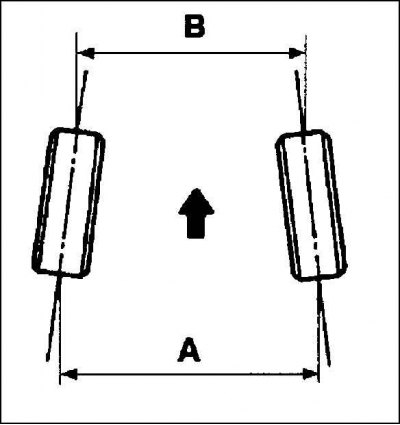
Accurate wheel alignment should only be performed in a branded workshop. In case of one-sided tire wear, the alignment should be checked primarily. The alignment is checked if parts of the steering trapezoid have been removed. The alignment can be checked with relatively simple means.
The above prerequisites for verification must be met.
1. Place the wheels straight ahead, the steering wheel crossbar should be horizontal.
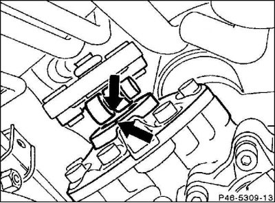
2. The middle position is reached when the groove at the steering joint aligns with the marking mark on the steering gear (arrow). If the steering wheel is not quite straight, remove it and reposition it.
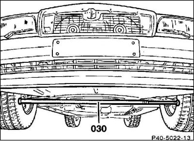
3. Place an extendable bar between the front wheels and extend it with a force of about 100 N (corresponds to 10 kg). To do this, use the branded special equipment or a similar bar. The extension is necessary to simulate the movement when the wheels tend to move outward.
4. Measure the toe-in. The overall toe-in of the front wheels should be 0°25'±10' (for sports suspension 0°10'±10'). This means that the edges of the rim at the front should be 1 mm closer than at the rear.
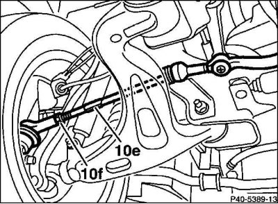
5. Set the positive toe-in by rotating the steering linkage lever by the Allen key (10e). First, release the clamping cone (10f), while holding the lever by the Allen key with an open-end wrench.
6. Set the toe-in to the same angle on the left and right, with the steering wheel in the middle position.
7. Tighten the clamping cone (10f) to 50 Nm, holding the steering linkage lever by the Allen key with an open-end wrench. Check the ball joint seal, it should not be crushed or damaged. After checking (installing), remove the wheel spacer.