
Cars BMW Cars Volkswagen Cars Chevrolet Cars Land Rover Cars Lada Cars Honda Cars Peugeot
English Русский
Български
Беларускі
Український
Српски
Hrvatski
Română
Polski
Slovenský
Magyar
Bookmark News and articles Sitemap Feedback Site search
MercedesMan.ru


A-Class C-Class E-Class G-Class M-Class S-Class Others
190 (W201) (1982-1993) W202 (1993-2000) W203 (2000-2007)
  • Main
  • C-Class
  • W201 (1982-1993)
  • Power unit
  • Exhaust system
  • Turbocharger — removal and installation

Turbocharger — removal and installation (Mercedes-Benz C-Class W201)

0
Contents: Basic information ↡ Removal ↡ Installation ↡

Basic information


1. The turbocharger is mounted under the exhaust manifold. Lubrication is provided by a special oil supply pipe, which is screwed into the cylinder head. The oil returns to the pan through a return pipe, which is connected to the side surface of the cylinder. The turbocharger has a built-in turbine bypass valve and a vacuum diaphragm, which is used to limit the air pressure entering the intake manifold.

2. Turbocharger parts rotate at very high speeds and are therefore very sensitive to contamination. Small dust particles can cause significant damage to the compressor, especially if they get on the turbine blades. Before working on the turbine, read the precautions and warnings below.

Warning: Thoroughly clean the area around all tube connections before disconnecting them. This will prevent dirt from getting inside the tubes. To prevent contamination, store removed parts in a closed container. Cover the turbocharger air ducts to prevent debris from getting inside and clean only with a lint-free cloth.


Precautions: Do not start the engine with the compressor air pipe disconnected: the vacuum in the intake increases very quickly if the engine speed increases and there is a risk of foreign particles being sucked in and then ejected at very high speed.


Removal


3. Disconnect the negative battery terminal.

4. Where provided, remove the lower engine shield as described in Chapter 11.

5. Where necessary, refer to the appropriate section of this Chapter and remove the air cleaner. On vehicles equipped with an oxidation trap, remove the screw and heat shield located between the air cleaner and the oxidation trap.


6. Loosen the latches and disconnect the air cleaner hose to the turbocharger (see fig. 6.6).
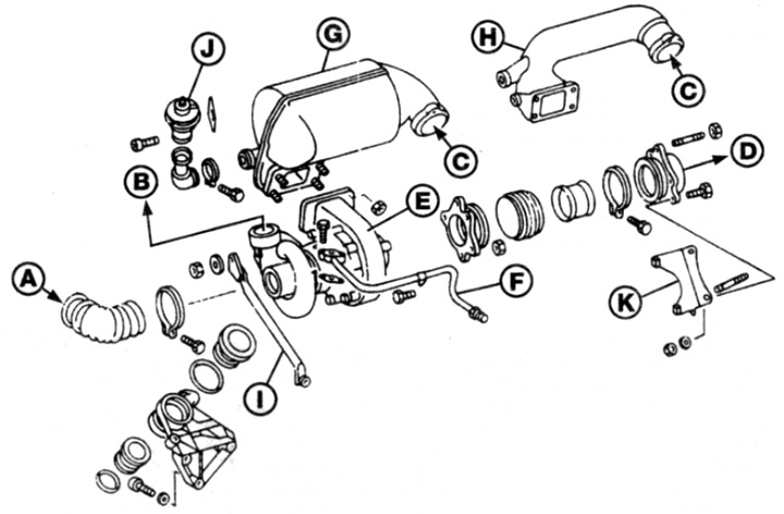
Fig. 6.6. Turbocharger unit

Fig. 6.6. Turbocharger unit
A From the air purifier
B To the intake manifold
C From the exhaust manifold
D To the exhaust pipe
E Turbocharger
F Oil pipe
G Oxidation trap
H Air charging tube
I Support stand
J EGR valve
To Bracket


7. Disconnect the vacuum hoses from the compressor bypass valve diaphragm housing and, where applicable, the EGR valve. Note the hose locations and color coding for easy reinstallation.

8. Where provided, loosen the fasteners, then disconnect and remove the bellows housing from the EGR valve base.

9. Where provided, unscrew the nuts and remove the oxidation trap from the exhaust manifold together with the bracket. Note: On cars without a trap, an intermediate pipe is installed in its place.

10. Loosen the clamps and disconnect the pipe from the turbocharger to the intake manifold.

11. Unscrew the clamps and disconnect the mixing tube (where it is installed) based on the EGR valve from the turbocharger.

12. Loosen the fittings and disconnect the oil feed and return pipes from the turbocharger - be prepared for oil to spill. Remove the sealing washers and dispose of them - new ones will be required for installation. Release the oil feed pipe from the clamp on the intake manifold.


13. Unscrew the nuts and disconnect the exhaust pipe from the turbocharger outlet. Remove the gasket - a new one is required during installation.

14. Loosen and unscrew the bolts securing the compressor to the bracket and stand, remove the compressor from under the exhaust manifold.

Installation


15. The turbocharger is installed in the reverse order, taking into account the following points:
  • a) Before tightening the compressor mounting bolts to the bracket, hand tighten the exhaust manifold nuts.
  • b) Apply high temperature grease to the threads and heads of the new intermediate pipe/oxidizer trap mounting bolts. Then install and tighten them to specification.
  • c) Tighten the exhaust pipe nuts securely.
  • d) Before connecting the fittings and tightening them completely, fill the oil supply pipe and the turbocharger inlet pipe with clean engine oil.
  • d) Tighten the oil return pipe fitting securely.
  • e) Connect the vacuum hoses to the compressor bypass valve and EGR valve according to the notes made during removal.
  • g) When test running the engine after installation, let the engine idle for approximately one minute to allow the oil to distribute between the turbine shaft bearings.
This article is available at: russian, bulgarian, belarusian, ukrainian, serbian, croatian, romanian, polish, slovak, hungarian
The article has been verified: Lukyanov Nikita Ilyich
Share with friends:
◀ Previous
C-Class 190 (W201) / Exhaust system
Next ▶

Exhaust Gas Recirculation (EGR) System
Exhaust manifold — removal and installation
Crankcase ventilation system — basic provisions
Fuel vapor recovery system
Exhaust system: basic information
Exhaust system — basics and replacement of parts
Catalytic Converter — Basic Information and Precautions
Additional Air Supply System — Parts Removal and Installation
More similar articles for repairing other models

☛ Exhaust gas turbocharger Mercedes W168 (1997-2004)
☛ Turbocharger technical characteristics Mercedes W124 (1984-1995)
☛ Removal and installation of turbocharger (OM603) Mercedes W140 (1991-1998)
☛ Turbocharger — General Description Mercedes Sprinter (1995-2000, diesel)
Link in different formats to this article
Comments and feedback from visitors
No comments yet


How much will 39 + 39 ?


W203 (2000-2007) 
  • General information
  • Introduction to guide
  • User manual
  • Maintenance
  • Power unit
  • Gasoline engines
  • Diesel engines
  • Cooling system
  • Ventilation and heating
  • Supply system
  • Injection system (gasoline)
  • Injection system (diesel)
  • Exhaust system
  • Ignition and control system
  • Charge and launch systems
  • Transmission
  • Mechanical gearbox
  • Automatic gearbox
  • Clutch and drive shafts
  • Differential
  • Chassis
  • Brake system
  • Car suspension
  • Steering
  • Body
  • Exterior (external elements)
  • Interior (internal elements)
  • Electrical equipment
  • Equipment and devices
  • Lighting system
  • Electrical diagrams (2000)
  • Electrical diagrams (since 2001)
W202 (1993-2000) 
  • General information
  • User manual
  • Driving a car
  • Car care
  • Maintenance
  • Power unit
  • Gasoline engines
  • Diesel engines
  • Lubrication system
  • Cooling system
  • Heating and ventilation
  • Ignition system
  • Fuel system
  • Injection system (gasoline)
  • Injection system (diesel)
  • Exhaust system
  • Transmission
  • Clutch
  • Car gearbox
  • Chassis
  • Suspension, wheels and tires
  • Steering
  • Brake system
  • Body
  • Exterior (external elements)
  • Interior (internal elements)
  • Doors and windows
  • Electrical equipment
  • Equipment and devices
  • Power devices
  • Lighting system
  • Electrical circuits
190 (W201) (1982-1993) 
  • General information
  • Introduction to the guide
  • Operation and care
  • Maintenance (gasoline)
  • Maintenance (diesel)
  • Troubleshooting
  • Power unit
  • Petrol engine I4
  • Petrol engine V6
  • Diesel engines
  • Engine overhaul
  • Cooling and heating
  • Power system (carburetor)
  • Injection system (gasoline)
  • Injection system (diesel)
  • Exhaust system
  • Charge and start system
  • Ignition system (I4)
  • Ignition system (V6)
  • Diesel heating system
  • Transmission
  • Clutch
  • Mechanical gearbox
  • Automatic gearbox
  • Cardan shaft and axle shafts
  • Chassis
  • Brake system
  • Car suspension
  • Steering
  • Body
  • Exterior (external elements)
  • Interior (internal elements)
  • Doors, locks and windows
  • Electrical equipment
  • Equipment and devices
  • Electrical circuits
 
MercedesMan.ru © 2017–2026 · Mobile version · Read about Mercedes · Sitemap: EN BG BY UA RS HR RO PL SK HU · Feedback · Site search · Bookmark A-Class (W168) · C-Class (W201) · C-Class (W202) · C-Class (W203) · E-Class (W123) · E-Class (W124) · E-Class (W210) · G-Class (W463) · M-Class (W163) · S-Class (W116, petrol) · S-Class (W126, petrol) · S-Class (W140) · S-Class (W220) · Sprinter · Vito 1 · Vito 2 · Vario 814D ·
 
We only use cookies without which some of the site's features may not be available.