
Engine controls 112, 113
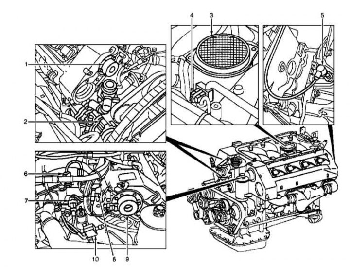
1 - Electromagnet for adjusting the right camshaft; 2 - Pump of the air mixing system (AIR); 3 - Thermometric air mass sensor (MAF); 4 - Electronic accelerator / Tempostat / Regulator x.x. (EA/CC/ISC); 5 - Intake air temperature sensor (IAT); 6 - Crankshaft position sensor (CKP); 7 - Coolant temperature sensor (ECT); 8 - Hall effect camshaft sensor; 9 - Electromagnet for adjusting the left camshaft; 10 - Valve for switching the pump of the air mixing system (AIR)
Elements of the ignition and injection control system for engines 112, 113
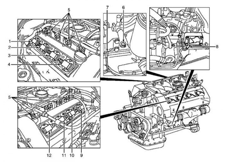
1 - Ignition coil No. 4; 2 - Ignition coil No. 3; 3 - Ignition coil No. 2; 4 - Ignition coil No. 1; 5 - Fuel injectors; 6 - D / oil level switch; 7 - Knock sensor 1 (right side of the engine); 8 - Knock sensor 2 (left side of engine); 9 - Ignition coil No. 8; 10 - Ignition coil No. 7; 11 - Ignition coil No. 6; 12 - Ignition coil #5
Location of control units in the car
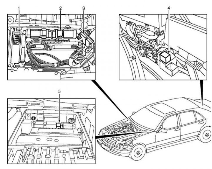
1 - Basic module; 2 - Engine control unit ME-SFI; 3 - Control unit box; 4 - Fuel pump relay module; 5 - Relay module for air mixing system (AIR)
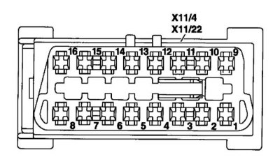
Engine control unit connectors and pin assignment
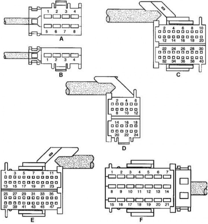
1A - Left top-flow heated lambda probe (1); 2A - Supply voltage (circuit 87), protected by a fuse; 3A - Grounding; 4A -; 5A - Right upper flow heated lambda probe (1); 6A - Fan control of engine cooling / climate control systems; 7A - Grounding; 8A - Grounding; 1B - Right downstream heated lambda probe (2) (USA only); 2B - Left lower flow heated lambda probe (2) (USA only); 3B - DLC diagnostic connector; 4V - Supply voltage (circuit 30); 1С ÷ 20С —; 21C - Adsorber purge valve; 22C - Pedal position sensor (+ nominal value potentiometer 1); 23C - Pedal position sensor (- nominal value potentiometer 1); 24C - Pedal position sensor (potentiometer nominal value 1 cleaner); 25С - Pedal position sensor (potentiometer nominal value 2 cleaner); 26C - Pedal position sensor (- nominal value potentiometer 2); 27C - Pedal position sensor (+ nominal value potentiometer 2); 28C - AIR system air pump relay module (USA only); 29C - Fuel pump relay module (K27); 30C -; 31С - Grounding of the right upper flow lambda probe 1; 32С - Signal of the right upper flow lambda probe 1; 33C - Signal of the left upper flow lambda probe 1; 34С - Grounding of the left upper flow lambda probe 1; 35С ÷ 37С —; 38C - Diagnostic connector (engine speed signal); 39C - Diagnostic connector (ME-SFI DTC); 40С - Signal (contour 50); 1D - Fuel pump relay module (K27); 2D - Carbon adsorber shut-off valve (USA only); 3D - Starter relay; 4D - Ground pressure sensor in the fuel tank (USA only); 5D - Fuel tank pressure sensor signal (USA only); 6D - Supply voltage 5V for the pressure sensor in the fuel tank (USA only); 7D - Grounding the right downstream lambda probe (USA only); 8D - Right downstream lambda probe signal (USA only); 9D - Signal of the left lower flow lambda probe (USA only); 10D - Grounding the left downstream lambda probe (USA only); 11D - CAN data bus «H»; 12D - CAN data bus «L»; 13D - Variable speed adjustment (only without DAS 3); 14D ÷ 15D -; 16D - Collision signal; 17D ÷ 18D -; 19D - Determining the provisions of P/N AT; 20D - Tempo switch (acceleration / installation) (only without DAS 3); 21D - Tempo switch (engine braking/installation) (only without DAS 3); 22D - Tempo switch (return) (only without DAS 3); 23D - Tempo switch (control contact) (only without DAS 3); 24D - Tempo switch (off) (only without DAS 3); 1E - Injector of cylinder No. 6; 2E - Injector of cylinder No. 3; 3E - Injector of cylinder No. 7; 4E - Cylinder No. 8 injector; 5E - EGR switch valve; 6E ÷ 9E -; 10E - AIR system air pump switch valve (USA only); 11E -; 12E - Resonance valve-switch of the inlet pipeline; 13E - Cylinder 4 injector; 14E - Cylinder 2 injector; 15E - Voltage 5V, level / temperature / oil quality sensor; 16E - Grounding the level / temperature / oil quality sensor; 17E - Level / temperature / oil quality sensor signal; 18E ÷ 20E -; 21E - Oil pressure switch signal; 22E - Voltage 5V pressure sensor (USA only); 23E - Pressure sensor signal (USA only); 24E - Pressure sensor ground (USA only); 25E - Cylinder 1 injector; 26E - Cylinder 5 injector; 27E - AIR pump relay in relay module (USA only); 28E - Ground coolant temperature sensor (ECT); 29E - Coolant temperature sensor signal (ECT); 30E -; 31E - Actuator of the electronic gas pedal / tempostat / idle speed stabilization system (EA/CC/ISC) (current value potentiometer 1 cleaner); 32E - Actuator of the electronic gas pedal / tempostat / idle speed stabilization system EA / CC / ISC (actual value potentiometer ground); 33E - Supply voltage of the actual value potentiometer; 34E - Actuator of the electronic gas pedal / tempostat / idle speed stabilization system EA / CC / ISC (actual value potentiometer 2 ground); 35E ÷ 36E -; 37E - Grounding the CKP sensor; 38E - CKP sensor signal; 39E - Grounding the camshaft Hall effect sensor; 40E - Camshaft Hall effect sensor signal; 41E - Ground knock sensor 1 (KS1) (on the right side of the engine); 42E - Knock sensor signal 1 (KS1) (on the right side of the engine); 43E - Ground knock sensor 2 (KS2) (on the right side of the engine); 44E - Knock sensor signal 2 (KS2) (on the right side of the engine); 45E - Intake air temperature sensor (IAT) (built into the film air mass sensor [MAF]); 46E - Supply voltage 5V film sensor MAF; 47E - Signal 5V film sensor MAF; 48E - Ground 5V MAF film sensor; 1F - Actuator of electronic acceleration / tempostat / idle speed stabilization systems (EA/CC/ISC) (-); 2F - Actuator of EA/CC/ISC systems (+); 3F-; 4F - Ignition coil of the 3rd cylinder T1 / 3 b; 5F - Ignition coil of the 3rd cylinder T1 / 3 a; 6F - Ignition coil of the 4th cylinder T1 / 4 a; 7F - Ignition coil of the 4th cylinder T1 / 4 b; 8F - Ground; 9F - Ignition coil of the 8th cylinder T1 / 8 b; 10F - Ignition coil of the 8th cylinder T1 / 8 a; 11F - Ignition coil of the 7th cylinder T1 / 7 b; 12F - Ignition coil of the 7th cylinder T1 / 7 a; 13F - Ignition coil of the 5th cylinder T1 / 5 a; 14F - Ignition coil of the 5th cylinder T1 / 5 b; 15F - Ground; 16F - Ignition coil of the 6th cylinder T1 / 6 b; 17F - Ignition coil of the 6th cylinder T1 / 6 a; 18F - Ignition coil of the 2nd cylinder T1 / 2 b; 19F - Ignition coil of the 2nd cylinder T1 / 2 a; 20F - Ignition coil of the 1st cylinder T1 / 1 a; 21F - Ignition coil of the 1st cylinder T1 / 1 b
The main elements of electrical equipment, the location of ignition and fuel injection control units, sensors, valves and drive elements are shown in the illustrations.
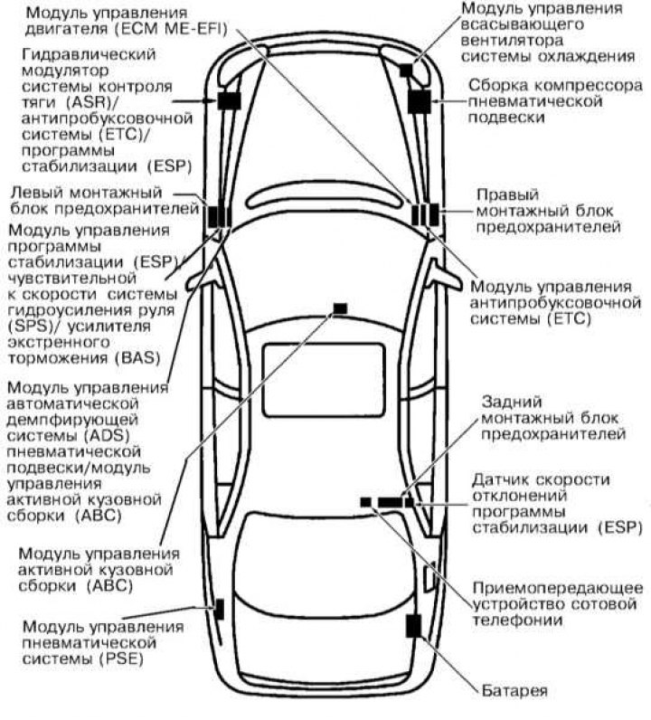
The location of the main electrical components in the car
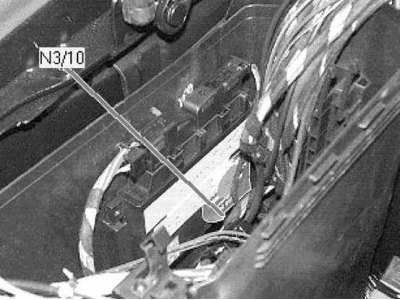
Location of the engine control unit (under the hood on the right, behind)
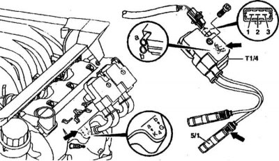
Dual ignition coils for two spark plugs A and B of the same cylinder
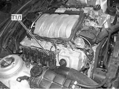
Coils of ignition of candles of the 1st cylinder (right side of the engine)
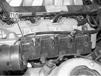
Coils of ignition of candles of the 5th cylinder (left side of engine)
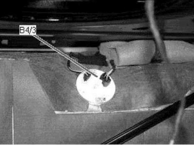
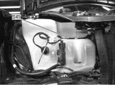
Fuel tank pressure sensor (front, center trunk)
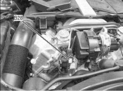
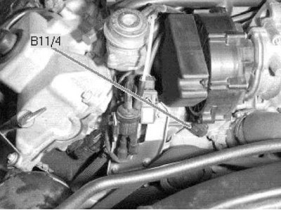
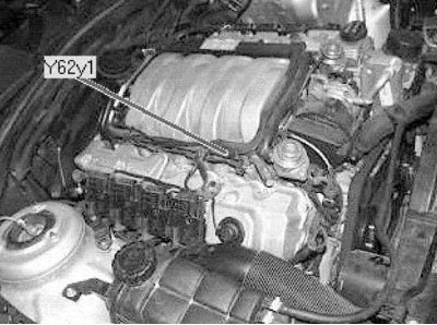
Pressure sensor B28 (front, top of the engine)

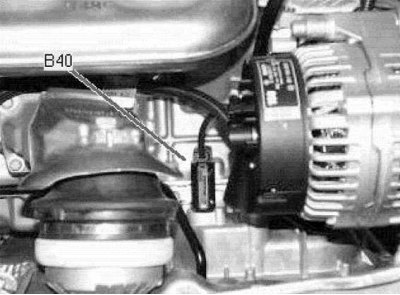
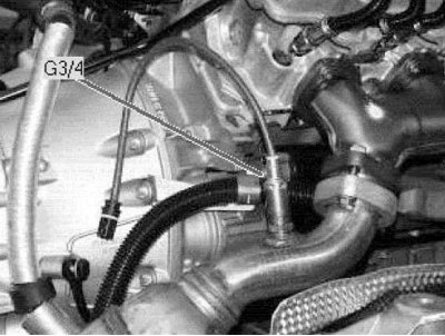
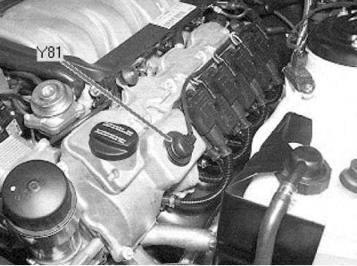
Intake air thermometer (rear, center of engine)
Oil pressure sensor (right side of engine, bottom)
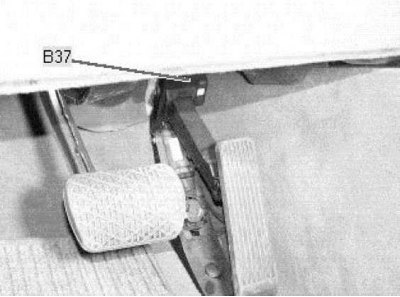
Accelerator pedal sensor
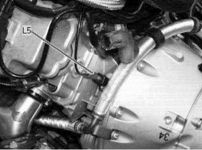
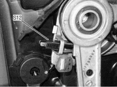
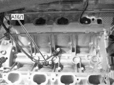
crankshaft position sensor (left rear of engine)

Camshaft hall sensor (right front of the engine)
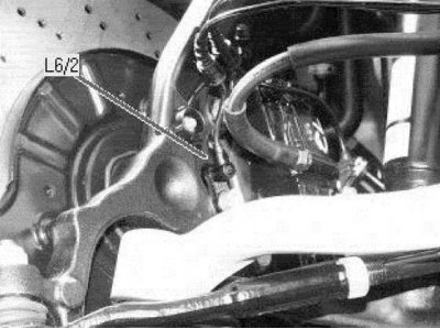
Vehicle speed sensor front right (wheel arch)
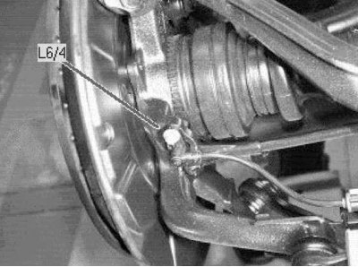
Vehicle speed sensor rear right (wheel arch)
Parking brake sensor (on the parking brake pedal)
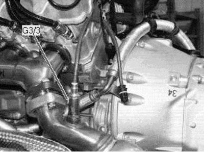
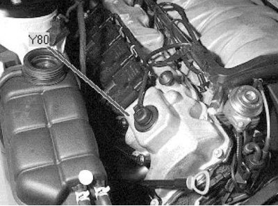
Coolant Temperature Sensor - ECT (engine front)
Coolant level sensor on the expansion tank
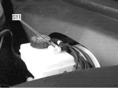
Brake fluid level sensor (on the tank - engine compartment on the left)
knock sensors
Diagnostic connector
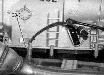
Left pre-catalytic lambda probe
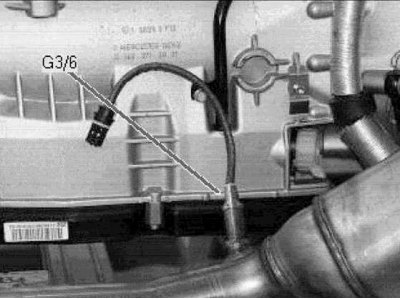
Right pre-catalytic lambda probe
Cylinder 1 injector (right side of the engine)
Shut-off valve of the left row of cylinders (left side of engine)
Shut-off valve of the right row of cylinders (right side of the engine)
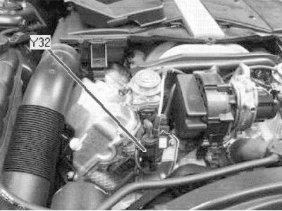
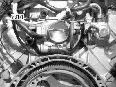
Exhaust air pump switching valve (engine front)
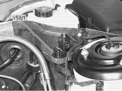
Canister purge control valve (left, rear of the engine compartment)
EGR Valve Vacuum Transmitter (back of the engine)
Left post catalytic lambda probe
Right post-catalytic lambda probe