



Contents: General information ↡ Preliminary checks ↡
Ignition control signal oscillograms
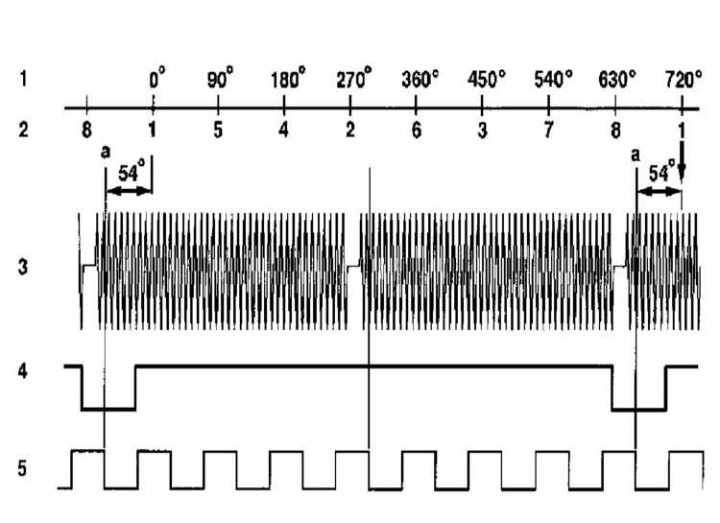
Please also refer to Section Using an Oscilloscope to Monitor Signals in Control System Circuits.
1 - Crankshaft rotation angle CKA; 2 - Cylinder number; 3 - Crankshaft position sensor L5 CKP signal; 4 - Signal from Hall sensor B6/1 camshaft position; 5 - TNA Engine Speed Signal
Functional diagram of the microprocessor control system for V6 and V8 ME SFI 2.0 engines
Information copied from the website (www.mercedesman.ru)
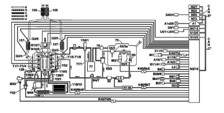
50 - Compressor; 55 - Fuel filter; 55/2 - Fuel pressure regulator 5.0 bar; 55/3 - Fuel pressure regulator 5.3 bar; 55/3a - Damper; 55/4 - Spray chamber; 71 - Check valve; 75 - Fuel tank; 76 - Ventilation valve; 77 - Carbon adsorber; 77/1 - Ventilation; 89 - EGR valve; 95 - Mixture pump; 110/2 - Charge air cooler; 110/10 - Low Temperature Cooler; 110/11 - Additional low-temperature cooler; 126/1 - Left secondary air mixing shut-off valve; 126/2 - Right secondary air mixing shut-off valve; 128 - Non-return vacuum valve; 157 - Three-function catalytic converter at the engine compartment bulkhead; 158 - Three-function catalytic converter under the bottom; A1 - Instrument panel; A1e58 - Engine Failure Diagnostic Indicator Lamp; A16/1 - Knock sensor 1 (right side of the engine); A16/2 - Knock sensor 2 (left side of the engine); B4 - Fuel level sensor; B4/7 - Fuel pressure sensor; B6/1 - Camshaft Hall Effect Sensor; B11/4 - Coolant Temperature Sensor (CTS); B17/8 - Charge air temperature sensor; B28/8 - Charge air pressure sensor ¹; B37 - Accelerator Pedal Position Sensor; B40 - Oil level/temperature/quality sensor; B40/2 - Cylinder Shut-Off System Oil Pressure Sensor ¹; CAN "B" - Data bus in the cabin; CAN "C" - Data bus in the engine compartment; G2 - Generator; G3/3 - Left pre-catalytic lambda probe; G3/4 - Right pre-catalytic lambda probe; G3/5 - Left post-catalytic lambda probe; G3/6 - Right post-catalytic lambda probe; K40/5kT - Fuel pump relay; K40/7kL - Starter relay; K40/7kN - Secondary air mixing system relay; K40/8kW - Blow-off air relay; K40/8kX - In-tank fuel pump relay; L5 - Crankshaft Position Sensor (CKP); L6/1 - Left front wheel sensor; L6/2 - Right front wheel sensor; L6/3 - Left rear wheel sensor; L6/4 - Right rear wheel sensor; M1 - Starter; M3 - Fuel pump; M3/1 - Pump built into the fuel tank; M4/7 - Electric fan of the engine and KV with built-in control unit; M16/6 - Throttle actuator; M16/7 - Air recirculation flap actuator; M33 - Electric Air Pump; M44 - Charge air cooler circulation pump; N₂/7 - Control unit for limiting systems; N3/10 - Fuel Injection Control Module (ME-SFI); N15/3 - Electronic Traction Control (ETC) Control Module; N15/5 - AT selector lever control unit; N₂2 - Additional Air Control System (AAC) Push Button Control Module; N47-1 - Traction Control System (ASR)/Speed-Sensitive Power Steering (SPS) Control Module; N47-5-Control unit for stabilization (ESP), SPS and brake booster (BAS); N73 - Electronic Ignition Switch Control Unit (EIS [EZS]); N80 - Steering column unit; N118 - Fuel pump control unit; S9/1 - Brake light switch sensor; S40/4 - Variable speed cruise control; T1/1 - T1/8 - Twin ignition coils for cylinders 1-8; X11/4 - Diagnostic connector DLC; Y2/1 - Electromagnetic clutch of the supercharger of the blower air; Y32 - Secondary Air Mixing System (AIR) Air Pump Switch Valve; Y58/1 - Evaporative Canister Purge Control Valve; Y62 - Fuel Injectors (LH-SFI, HFM-SFI, PEC [LH, HFM, PMS])
¹Only engine 113.960 with cylinder deactivation system (code 479)
Connecting the ignition coil connectors
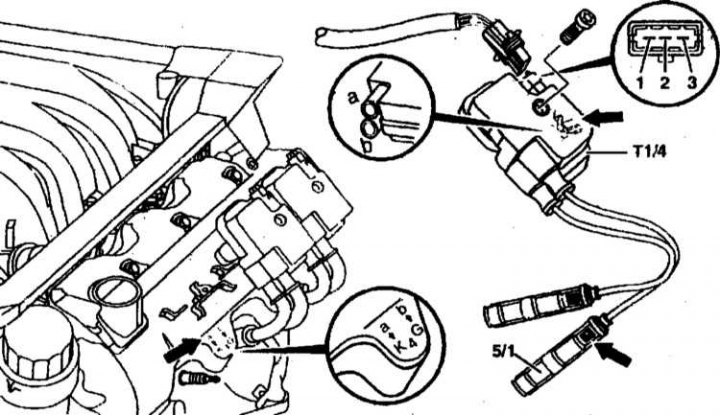
5/1 — HV wire tips
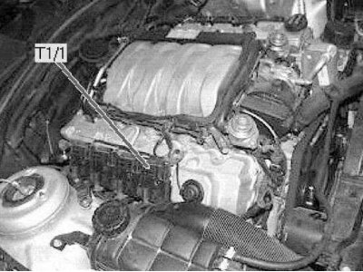
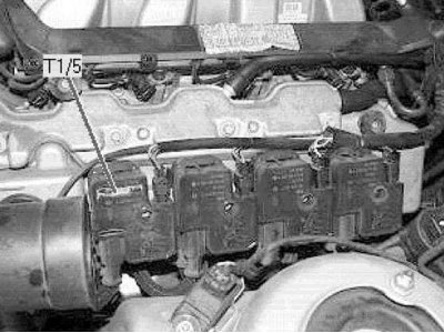
T1/1-T1/6 — Twin ignition coils for cylinders 1-6
3-pin connector:
1 - Chain 1b
2 - Chain 15
3 - Chain 1a
a and b — BB - connections
Ignition coil wiring diagram
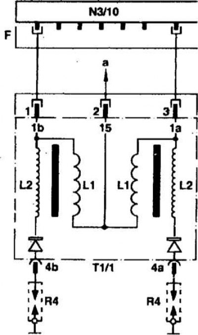
R4 - Candles; N 3/10 - Control unit; L1 - Primary windings; L2 - Secondary windings
 |
 |
Please also refer to Section Troubleshooting Introduction and the following Sections Self-diagnosis of electronic control systems of the second generation OBD II, Controller for interfacing a personal computer with an on-board OBD II self-diagnostic system according to SAE (PWM and VPW) and ISO 9141-2 protocols.
The ignition system and the fuel system are interrelated components of the engine management system. Although this chapter only discusses the ignition system, some of its components perform multiple functions related to the operation of the fuel system.
General information
The ignition system and the fuel system have a common diagnostic system designed to store fault codes and perform diagnostics. When a fault occurs, the control unit records a certain sequence of signals in memory (fault code), which can subsequently be considered a special device (refer to Section Self-diagnosis of electronic control systems of the second generation OBD II, which describes the procedure for checking the fuel system).
If there are malfunctions in the operation of the car engine, the cause can most likely be found out by examining the memory of the control unit. After reading the fault codes, it is possible to find out which unit is faulty and perform the appropriate tests (either the unit itself or its wiring).
Visual inspection of the wiring and connectors is not enough - be sure to read the information stored in the control unit's memory.
Preliminary checks
If the fault occurs shortly after servicing a component, first carefully inspect the component and its surroundings. The cause may be a poorly installed component or a poorly connected connector.
If you are trying to diagnose a specific engine problem, such as a loss of power, in addition to the steps below, measure the cylinder compression. Make sure the fuel filter and air cleaner have been changed at the recommended intervals.
Please note that after reading the fault codes, they must be deleted from the control unit memory using the same diagnostic scanner, and then the fault must be eliminated.
1. Open the hood and check that the battery terminals are securely connected and free of corrosion. If there is any corrosion or damage, replace or clean the cables. Similarly, check all grounding straps to make sure they are making good contact (the mating surfaces must be absolutely clean and free of any traces of corrosion) with a body or engine.
2. After this, carefully inspect all visible wiring laid inside the engine compartment. Make sure that all connections are secure. At this stage, you are interested in clearly damaged wires. They can be cut or chafed against sharp or moving engine components, such as suspension parts or a drive belt. A wire can break as a result of careless installation of a component. The wire can melt upon contact with the exhaust system. The most likely cause of wiring damage is improper routing of its bundles in the engine compartment after repair or maintenance of a component.
3. The wires may be damaged or shorted without damage to their insulation. In this case, inspection will not lead to anything. Such damage can occur after pulling the wires or improperly placing the wiring inside the engine compartment. If you think such damage is possible, check the wire following the sequence below.
4. A damaged wire can be repaired by soldering a piece of new wire into the gap. Soldering is necessary to obtain a reliable contact. Insulation can be restored with a sufficient amount of electrical tape or heat shrink tubing. If the damage is significant and the damaged wire plays a significant role, the most reliable way out is to (although quite expensive) the corresponding harness will be replaced with a new one.
5. After repairing the damaged wire, place it correctly in the engine compartment, away from rotating and hot parts. Do not forget to secure the wire in the intermediate clamps (if any).
6. Make sure all accessible connectors are secure and clean. All fasteners must be installed. If you notice any signs of corrosion on the inside of the connector, (white or green deposits, as well as traces of rust) or excessive contamination, remove it from the corresponding terminal and clean it thoroughly. You can use a special spray for this. If the connector is seriously damaged, it should be replaced. Keep in mind that in some cases you will have to replace the entire harness.
7. If you were able to completely remove traces of corrosion from the connector, fill it with preservative grease, then install it in place. You can find out the type of grease at the service station.
8. All models are equipped with a crankshaft position sensor (it is also used to determine the TDC of the first cylinder). Its working part may be contaminated with oil or dust, which can lead to malfunctions and, accordingly, misfires.
9. Carefully inspect all vacuum hoses and tubes located in the engine compartment. Make sure that the clamps are securely tightened and that there are no cracks, delaminations or signs of damage on the hoses themselves. Also make sure that no hoses are pinched or bent too much, i.e. do not let air through. Pay special attention to hoses located near sharp edges, as well as the ends of all hoses. All damaged hoses must be replaced.
10. Check the crankcase ventilation hoses for damage or contamination. Also check that they are not blocked from the inside. The number and locations of the system hoses depend on the vehicle model, but all models have a hose that connects the top of the engine to the air intake hose or intake manifold. The system hoses also connect the cylinder block (or oil filler neck) with an intake manifold. These hoses deliver oil vapors to the combustion chambers. If these hoses are dirty or blocked, the engine will run unstably (especially at idle).
11. Proceeding from the fuel tank through the fuel filter to the fuel distribution line along the fuel lines, carefully inspect them. If signs of damage or kinks are found, replace the corresponding section. Pay special attention to the pipe connections. Cracks may appear on them, leading to fuel leaks.
12. Remove the air cleaner housing cover and inspect the element. It should be relatively clean and dry. A heavily soiled air cleaner will provide significant airflow resistance, resulting in a noticeable reduction in engine power. Replace the air cleaner if necessary.
13. Start the engine and let it idle.
Warning! When performing any work in the engine compartment with the engine running, be extremely careful. In addition to the high probability of getting burned by hot engine or exhaust system parts, you risk getting seriously injured by rotating parts (for example, a radiator fan or a drive belt). Before starting work, first of all, take measures and observe safety precautions described at the beginning of each Chapter. Watch your hands, do not allow long hair or clothing to get into the engine compartment. Stay away from the exhaust system and other hot parts.
14. From the air intake to the air cleaner and then to the throttle body, check for leaks in the air supply hoses (including nearby vacuum hoses). They can be detected by a characteristic whistling sound. If there is no whistling sound, apply a small amount of soapy water to the suspect section of the hose. If the hose is damaged, the engine will change its operation and bubbles will appear on the treated surface of the hose (or, depending on the pressure in the hose, water may begin to be sucked in). If a leak is detected, tighten the clamp securely or replace the damaged hose.
15. Check the entire exhaust system in the same way (from manifold to rear section). Make sure there are no gas leaks. To make the job easier, you can lift the car on a lift, place it on a ramp or over a pit. To perform the simplest check, plug the exhaust outlet and listen to the system. If you hear a characteristic whistle, there is a leak. If a leak is detected, tighten the appropriate clamp, bolts or nuts, replace the gasket or burnt section.
16. Further testing involves moving each connector one by one on the corresponding terminal with the engine running. A poor contact will be determined by a change in the nature of the engine operation. Restore the reliability of the contact by replacing or cleaning the corresponding connector. Keep in mind that in some cases, entire harnesses will have to be replaced.
17. If, as a result of preliminary checks, you have not found the cause of unstable engine operation, the car should be taken to a service station for a more thorough diagnosis using special equipment.