
12V incandescent lamps | ||
To be able to change the lamp at any time, you should always have a box with the most important spare lamps in your car. | ||
Destination | Base, Type | Power, W |
Anti-fog headlight | H1 | 55 |
parking lights | W | 5 |
high beam | H7 | 55 |
dipped beam | H7 | 55 |
Direction indicator lamp | PY | 21 (yellow) |
Left relay and fuse box K40/6 engine compartment
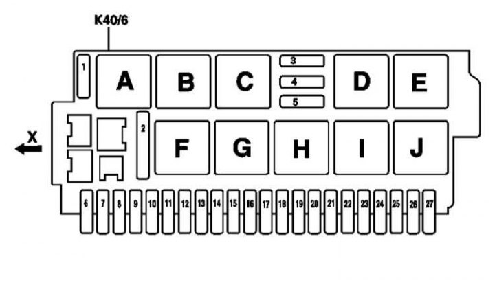
1-91 - fuses
A-X - relay
X - the direction of the car
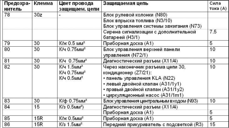
Fuse | Chain | Wire color is protected. chains | Protected circuit | Current (A) |
1 | 87 | — | Relay for heated wiper blades (K40/6kA) | 40 |
2 | 87 | — | Relay for discharge/exhaust pumps (K40/6kF) | 50 |
3 | 30 | — | Horizontal steering column adjustment: • Relay 1 longitudinal adjustment of the steering column (K40/6kD) • Relay 2 longitudinal adjustment of the steering column (K40/6kE) | 15 |
4 | 30 | — | Vertical adjustment of the steering column: • Steering column angle adjustment relay 1 (K40/6kI) • Relay 2 for steering angle adjustment (K40/6kJ) | 15 |
5 | 15R (since 09.2002 - 15) | — | Relay ON/OFF wiper (K40/6kH) | 40 |
6 | 15 (since 09.2002 - absent) | B/F 0.75 mm2 (since 09.2002 - absent) | Add-on switch heater (S4/3) (since 09.2002 - absent) | 7.5 (since 09.2002 - absent) |
7 | 15 (since 09.2002 - absent) | – | — | — |
8 | 30 (since 09.2002 - absent) | — | — | — |
9 | 30 | B/w 1.5 mm2 | with air suspension: • Airmatic system control unit with ADS (N51) in the presence of an active body clearance control system (ABC): • ABC system control unit (N51/2) | 30 |
10 | 15 | H/g 0.75 mm2 | Washer pump (M5/1) | 15 |
11 (from 09.2002 - only on models for Japan) | 15R | B/s 1.5 mm2 (from 09.2002 - B/W 0.5 mm2) | Cigarette lighter with illuminated front ashtray (R3) (from 09.2002 – point X137/1 of VISC power separation) | 15 (since 09.2002 - 5) |
12 | 15R | R/z 0.5 mm2 (since 09.2002 - absent) | Dynamic locking of the seat belt (A60) (since 09.2002 - absent) | 7.5 (since 09.2002 - absent) |
13 | 30 | R/h 4.0 mm2 | Front left door control unit (N69/1) | 40 |
14 | 15R | — | — | – (since 09.2002 - 10) |
15 | 30 | — | — | – (from 09.2002 - 30) |
16 | 15R | H/g 0.5 mm2 | Stoplight switch (S9/1) | 7.5 |
17 | — | — | — | — |
18 | 15R | B/W 0.75 mm2 B/W 0.5 mm2 | If you have a GSM mobile phone (D2B) (basic equipment) (code 317): • mobile phone plug (X39/39) If you have an MB GSM phone (D2B) (code 316): • D2B interface for landline phone (A59) If you have an MB GSM phone (D2B) (code 316) with Tele Aid emergency call system (code 347): • control unit of the Tele Aid system (A35/8) If you have an MB GSM phone (D2B) (code 316) with E-Call emergency call system (code 349) via cable connector terminal 15R (Z3/12): • D2B interface for landline phone (A59) • range control unit (N96) • control unit of the E-Call system (A35/8) (from 09.2002 – With MB GSM phone (D2B) (code 854): • via connector 15R (Z3/1) circuit 2: - frequency selection control unit (N96) - E-call control unit (A35/8) - D2B interface for mobile phone (A59/1) | 5 |
19 | 15 | – (since 09.2002 – K/W 0.5 mm2) | – (from 09.2002 - front left (A76) and right (A76/1) reversible emergency tensioners) | – (since 09.2002 - 5) |
20 | 15 | B/W 0.5 mm2 (since 09.2002 - absent) | Dashboard (A1) Diagnostic connector (X11/4) (since 09.2002 - absent) | 5 (since 09.2002 - absent) |
21 | 15R | B/W 0.5 mm2 (since 09.2002 - absent) | Dashboard (A1) (since 09.2002 - absent) | 5 (since 09.2002 - absent) |
22 | 30 | Red 0.75 mm2 (since 09.2002 - 2.5 mm2) | Dashboard (A1) (since 09.2002 - Radio (A2) control panel with COMAND system display (A40/3)) | 5 (since 09.2002 - 15) |
23 | 30 | K/W 1.5 mm2 K/W 0.75 mm2 K/W 0.5 mm2 K/W 0.75 mm2 (from 09.2002 - K/W 0.75 mm2) | Via cable connector terminal 30 KLA (Z7/21): • KLA control panel (N22) • circulation pump (A31/1m1) • left double valve (A31/1y1) • right double valve (A31/1y2) (from 09.2002 - With TV tuner (code 860): TV tuner (A2/10) If you have a TV tuner (code 860): Via connector (Z4/3) chain 30 models for Japan:- TV tuner (A2/10) - radio with CD changer (A2/16)) | 10 |
24 | 30 | K/g 0.75 mm2 (since 09.2002 - C/W 2.5 mm2) | Diagnostic connector (X11/4) (from 09.2002 - audio input control unit) | 10 (since 09.2002 - 20) |
25 | 30 | – (since 09.2002 - C/W 2.5 mm2) | – (since 09.2002 – Sound amplifier (A2/13)) | – (since 09.2002 - 25) |
26 | 30 (since 09.2002 - absent) | K/h 0.75 mm2 (since 09.2002 - absent) | Top control panel (N72/1) (since 09.2002 - absent) | 10 (since 09.2002 - absent) |
27 | 30 | — | — | — |
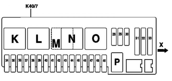
Right relay and fuse box K40/7 engine compartment
Fuse | Chain | Wire color is protected. chains | Protected circuit | Current (A) |
28 | 30 | – | Horn relay (K40/7kP) | 15 |
29 | 87 | – | Relay for electronic engine and chassis control systems (K40/7kK) | 20 |
30 | 87 | – | Relay for electronic engine and chassis control systems (K40/7kK) | 20 |
31 | 87 | – | Air pump relay (K40/7kN) | 40 |
32 | 87 | – | Air compressor relay (K40/7kO) | 40 |
33 | 30 | Red 4.0 mm2 | Heating air circulation unit (A32) | 40 |
34 | 87 | Red 0.5 mm2 (since 09.2002 - 1.0 mm2) | Traction control control unit (N47) | 5 (since 09.2002 - 10) |
35 | 30 | – (since 09.2002 - 1.5 mm2) | – (from 09.2002 - With steering wheel heating (code 443): Steering wheel heater (R22/4)) | – (since 09.2002 - 15) |
36 | 87 | K 0.5 mm2 | With Distronic (code 219a): DTR system control unit (N63/1) | 7.5 |
37 | 87 | Red 1.5 mm2 Red 0.75 mm2 | cable connector cl. 87 (Z7/5): • control unit of the electronic module of the control lever АТ (N15/5) • control unit of the EGS system (N15/3) | 15 |
| 38 (USA) (from 09.2002 - all models) | 30 | K/h 0.5 mm2 | Interior trunk lid actuation button (KIT) | 5 |
39 | 30 | R/h 4.0 mm2 | Front right door control unit (N69/2) | 40 |
40 | 15 | K 0.75 mm2 | In the presence of xenon. headlights (code 612b): headlight beam throw control unit (N71) | 10 |
41 | 30 | K 2.5 mm2 K 0.75 mm2 | If there is an autonomous heating system (code 228): via cable gland terminal 30 (solder sleeve in wiring harness) (Z7/26): • heater (STH) or add. Heater (ZUH) (A6) • radio remote control receiver STH (A6/1) | 20 |
42 | 30 | H/g 1.5 mm2 | • via cable connector class. 87 (Z7/24) (until 09.2002): - auxiliary relay fan unit (K25) | 20 |
| 43 (from 09.2002 - 43 OM628 and OM 648) | 87 | K/g 4.0 mm2 K/g 2.5 mm2 K/g 0.5 mm2 | For diesel engines only: • via cable connector terminal 87 (Z7/47) (until 09.2002):- CDI control unit (N3/9) - starter relay (K40/kL) in the front right relay and fuse box (K40/7) | 25 |
| 44 OM613 (from 09.2002 - 44 OM628 and OM648) | 87 | short 1.5 mm2 short 1.0 mm2 (since 09.2002 - 0.75 mm2) | For diesel engines only: • CDI control unit (N3/9) • heating of the inlet pipeline, in the front right box of relays and fuses (K40/7) | 7.5 |
| 44 OM628 | 87 | short 2.5 mm2 short 1.5 mm2 short 0.5 mm2 short 0.75 mm2 | via cable connector terminal 87D2 (Z7/48) (until 09.2002): • CDI control unit (N3/9) • starter relay (K40/kL) in the front right relay and fuse box (K40/7) • electric fan-supercharger of the engine and air conditioner with built-in regulator (M4/7) • low temperature circuit circulation pump (M44) | 10 |
45 | — | — | — | — |
46 | 87 | B/W 0.5 mm2 (since 09.2002 -) | With an active body height control system (ABC): • ABC system control unit (N51/2) With air suspension: • Airmatic system control unit with ADS (N51) | 5 |
47 | 15 | H/g 0.75 mm2 H/g 0.5 mm2 H/g 0.75 mm2 (until 09.2002) H/g 0.5 mm2 (until 09.2002) | Multifunction sensor KLA (B31/1) Fan electric motor in a protective box of electrical equipment (M2/2) Multifunction sensor KLA (B31/1) (until 09.2002) relay control fan unit of the engine cooling system or AT oil (K25) via plug connector (X22/3) (until 09.2002) Through the cable electric circuit of the fans (Z5/1) (until 09.2002) • multifunctional sensor KLA (B31/1) (until 09.2002) • relay control add. fan unit of the engine cooling system or oil in AT (K25) via plug connector (X22/3) (until 09.2002) • fan electric motor in a protective box of electrical equipment (M2/2) (until 09.2002) | 10 |
| 48 M112/113 (since 09.2002 - 48) | 15 | B/F 0.5 mm2 (since 09.2002 - missing) | Blower fan control unit (N65/2) (since 09.2002 - missing) | 7.5 (since 09.2002 - missing) |
| 48 M137 (since 09.2002 - 48) | 15 | B/F 0.5 mm2 (since 09.2002 - missing) | Electric fan-supercharger of the engine and air conditioner with built-in regulator (M4/7) (since 09.2002 - missing) | 7.5 (since 09.2002 - missing) |
49 | 15 | B/W 1.5 mm2 B/W 1.5 mm2 H 1.0 mm2 (from 09.2002 - B/W 1.0 mm2) | Via cable connector on protected terminal 15 (Z3/29): • ignition coils (T1/1) - (T1/8) • radio noise suppression capacitor (C4), for Japan and USA | 15 |
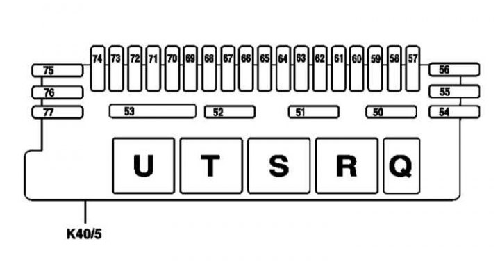
Rear relay and fuse box K40/5
Fuse | Chain | Wire color is protected. chains | Protected circuit | Current (A) |
50 | — | — | Rear window blind relay (K40/5kQ) | 10 |
51 | — | — | Towing protection relay (K40/5kR) | 5 |
52 | 30 (since 09.2002 - missing) | – | Fuel pump relay (K40/5kT) | 30 |
53 | 30 | – | Heated rear window relay (K40/5kU) | 50 |
54 | 15 | Canned 0.75 mm2 | Trailer detection control unit (N28/1) | 10 |
55 | 30 | Film 2.5 mm2 | Tow hitch socket, 13-pin (X58) | 25 |
56 | 30 | Red 2.5 mm2 | Trailer detection control unit (N28/1) | 30 |
57 | 30 | K 2.5 mm2 | With remote drive trunk lid (HDFS): • via cable connector terminal 30 (solder sleeve in wiring harness) (Z7/26) (since 09.2002 - Z7/32): - trunk lid release relay (K69/1) - trunk lid close relay (K69/2) – since 09.2002 – hydraulic pump | 25 |
58 | 30 | S/h 0.75 mm2 | Protected via cable connector. terminals 30, Keyless-Go system (Z7/19): • Keyless Go system control unit (N69/5) • Antenna Keyless Go front left door (A2/38) • Antenna Keyless Go rear left door (A2/39) • Antenna Keyless Go front right door (A2/40) • Keyless Go antenna rear right door (A2/41) • power electromagnet Keyless Go front left door (L12) • power electromagnet Keyless Go rear left door (L12/1) • power electromagnet Keyless Go front right door (L12/2) • power electromagnet Keyless Go rear right door (L12/3) | 7.5 |
59 | 30 | Paper 2x2.5 mm2 (since 09.2002 - 1x2.5 mm2) | Multifunctional control unit spec. a/m (MSS) (N26/9), taxi only | 30 |
60 | 15 (from 09.2002 - 30) | – (since 09.2002 - 0.75 mm2) | – (from 09.2002 rear window aerial amplifier unit (A2/12) X137/1 VISC power split point) | 7.5 |
61 (Japan) | 30 | Red 1.5 mm2 Red 0.75 mm2 Red 1.5 mm2 Red 0.75 mm2 Red 1.5 mm2 Red 1.5 mm2 Red 0.5 mm2 Red 0.75 mm2 Red 0.5 mm2 Red 0.75 mm2 | If you have a radio (D2B): • via cable connector class. thirty (Z4/3):- radio (A2) - aerial amplifier module above the rear window (A2/12) from 09.2002 - E-Call control unit (N112) - hands-free control unit (A35/1) If you have a radio (D2B) with CD changer (code 819): • via cable connector class. thirty (Z4/3):- radio (A2) - aerial amplifier module above the rear window (A2/12) – CD player with changer (in the trunk) (A2/6) In the presence of a communication and navigation system (COMAND): • control panel with COMAND display (A40/3) • via cable connector class. thirty (Z4/3):– phone plug, terminal 15C (X39/40) - TV tuner (A2/10), for Japan - video decoder (A2/11) – terminal 15 unloading relay (K41) | 15 |
61 | 30 | Red 1.5 mm2 Red 0.75 mm2 Red 1.5 mm2 Red 0.75 mm2 Red 1.0 mm2 Red 1.5 mm2 Red 0.75 mm2 | If you have a radio (D2B): • via cable connector class. thirty (Z4/3):- radio (A2) - aerial amplifier module above the rear window (A2/12) If you have a radio (D2B) with CD changer (code 819): • via cable connector class. thirty (Z4/3):- radio (A2) - aerial amplifier module above the rear window (A2/12) – CD player with changer (in the trunk) (A2/6) In the presence of a communication and navigation system (COMAND): • control panel with COMAND display (A40/3) • via cable connector class. thirty (Z4/3):– control panel with COMAND display (A40/3n1) - aerial amplifier module above the rear window (A2/12) - navigation computer (A40/3n2) - TV tuner (A2/42), for Europe and USA | 15 |
61 | 30 | Red 1.0 mm2 Red 1.5 mm2 Red 0.75 mm2 | In the presence of a communication and navigation system (COMAND) with traffic memory: • control panel with COMAND display (A40/3) • via cable connector class. thirty (Z4/3):– control panel with COMAND display (A40/3) – traffic data memory (A2/43) - navigation computer (A40/3n2) - aerial amplifier module above the rear window (A2/12) | 15 |
61 | 30 | R/h 1.5 mm2 K/h 0.5 mm2 K/h 0.75 mm2 K/h 0.5 mm2 R/h 1.5 mm2 K/h 0.75 mm2 | If you have an MB GSM phone (D2B) (code 853) with Tele Aid emergency call system (code 855): • phone support through connector tip (in the wiring harness) (Z28/30):- Tele Aid system control unit (A35/8) - phone transceiver, D2B (A35/13) • through the connector lug (Z7/46) circuit 30: - voice control system control unit (А35/11) If you have an MB GSM phone (D2B) (code 854): • D2B interface for mobile phone (A59/1) • compensator (A28/3) • through the connector lug (Z7/46) circuit 30: - voice control system control unit (А35/11) If you have an MB GSM phone (D2B) (code 854) with E-Call emergency call system (code 349) • through the connector lug (Z7/26) circuit 30:- E-call control unit (N112) - voice control system control unit (А35/11) - E-net compensator (A28/3) - D2B interface for mobile phone (A59/1) • through the connector lug (Z7/46) circuit 30: - voice control system control unit (А35/11) If you have a GSM mobile phone (D2B) (basic equipment) (code 380): • mobile phone plug (X39/39) • D2B interface for mobile phone (A59/1) | 15 |
62 | 30 | R/h 1.5 mm2 | Pneumatic control unit with combined functions (A37) | 20 |
63 | 30 | K/h 0.75 mm2 K/h 0.5 mm2 K/h 0.75 mm2 (since 09.2002 - 4.0 mm2) | If you have a D2B phone (code 316): • D2B interface for landline phone (A59) • phone transceiver (A35) with an emergency call system (TELE AID), • control unit of the TELE AID system (A35/8) or If you have a D2B phone (code 316) with voice control system (813b): • via cable connector terminal 30 (solder sleeve in wiring harness) (Z7/26):– D2B interface for landline phone (A59) - phone transceiver (A35) – voice control system control unit (A35/11) with an emergency call system (TELE AID), – control unit of the TELE AID system (A35/8) If you have a D2B mobile phone (code 317) (basic equipment): • mobile phone plug (X39/39) • traffic data memory (A2/43) (from 09.2002 - pneumatic pump for seat control (М40/1)) | 7.5 (since 09.2002 - 30) |
64 (Japan) | 30 | Red 0.75 mm2 (since 09.2002 - K/box 2.5 mm2) | • control panel with COMAND display (A40/3) • aerial amplifier module above the rear window (A2/12) (from 09.2002 - Left front seat adjustment control unit with memory function (N32/1)) | 7.5 (since 09.2002 - 25) |
65 | — | — | — | — |
66 | 30 | Red 2.5 mm2 (since 09.2002 - Film 2.5 mm2) | If you have a radio (D2B) with acoustic system (code 810): • sound amplifier (A2/13) (from 09.2002 - Right front seat adjustment control unit with memory function (N32/2)) | 25 |
67 | 30 | K/g 2.5 mm2 | Rear seat control unit (N25/6) | 25 |
68 | 30 | B/w 1.0 mm2 B/w 0.8 mm2 Paper 0.5 mm2 Paper 0.5 mm2 B/w 0.8 mm2 | via cable connector thirty (Z7/40): • rear air conditioner control unit (N22/4) • refrigerant shut-off valve in the rear air conditioner (Y67) • rear heating pump unit (A31/1) - circulation pump (A31/1m1) - left double valve (A31/1y1) - right double valve (A31/1y2) | 15 |
69 | 30 | R/h 1.0 mm2 | With air conditioning in the rear: 15 rear air conditioner control unit (N22/4) | |
70 | 30 | K/h 0.75 mm2 | RDK system control unit (N88) | 10 |
71 | 30 | C/cf 2.5 mm2 (from 09.2002 - K 6.0 mm2) | Left front seat adjustment control unit with memory function (N32/1) (from 09.2002 - front left emergency seat belt tensioner (A76)) | 25 (since 09.2002 - 40) |
72 | 30 | K 2.5 mm2 short 4.0 mm2 | Rear left door control unit (N69/3) | 40 |
73 | 30 | Film 2.5 mm2 (from 09.2002 - K 6.0 mm2) | Right front seat adjustment control unit with memory function (N32/2) (from 09.2002 - front right emergency seat belt tensioner (A76)) | 25 (since 09.2002 - 40) |
74 | 30 | K 4.0 mm2 K/g 4.0 mm2 | Rear right door control unit (N69/4) | 40 |
75 | 15 | B/C 1.5 mm2 | With Parktronic (code 220a): PTS control unit (N62) | 10 |
76 | 30 | K/g 1.5 mm2 | Refrigerator box in the back of the rear seat (A39/1) | 15 |
77 | 30 | R/h 2.5 mm2 | Ceiling control panel (N70) | 40 |
Front Panel
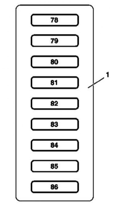
Models from 09.2002
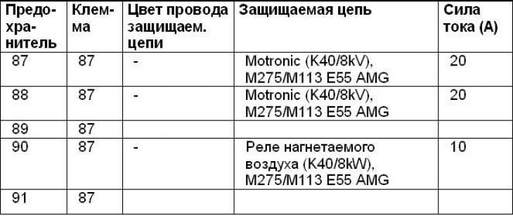
Right front box K40/8 engine compartment
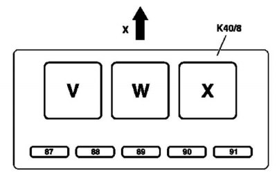
Relay assignment
Relay | Purpose A Relay for heated wiper blades (K40/6kA) B Relay circuit 15 (K40/KB) C Relay circuit 15 (K40/KC) D Relay 1 longitudinal adjustment of the steering column (K40/6kD) E Relay 2 longitudinal adjustment of the steering column (K40/6kE) F Relay for discharge/exhaust pumps (K40/6kF) G Relay positions 1 and 2 wiper blades (K40/6kG) H Relay ON/OFF wiper (K40/6kH) i Tilt steering relay 1 (K40/6kI) J Relay 2 steering column angle adjustment (K40/6kJ) K Relay for electronic engine and chassis control systems (K40/7kK) L Starter relay (K40/7kL) M Diesel models only: CDI relay (K40/7kM) N Air pump relay (K40/7kN) O Air compressor relay (K40/7kO) P Horn relay (K40/7kP) Q Rear blind relay (K40/5kQ) R Towing protection relay (K40/5kR) S Relay circuit 15 (K40/5kP) T Fuel pump relay (K40/5kP) U Rear defroster relay (K40/5kU) V Motronic relay (K40/8kV) W Air boost relay (K40/8kW) X In-tank fuel pump relay (only AMG) (K40/8kX) |