
Note. Separate characteristics are also given in the text of the Chapter and, if they are mandatory, are highlighted in bold.
Common parameters | |
Incandescent lamps | 12 V |
Purpose | Base, Type Power, W |
high beam | H7/D2R 55/35 |
dipped beam | H7/D2R 55/35 |
Fog lights | HB4 55 |
Front direction indicators | PY 21 |
parking light | W 5 |
Side turn signal repeaters | WY 5 |
Rear direction indicators | PY 21 |
Stop lights | R 21 |
misty lanterns | R 21 |
reversing lights | R 21 |
License plate lights | From 5 |
parking lights | R 4 |
Interior lamps / luggage compartment lighting | From 10 |
H7HB4 | Halogen lamp (clip fastening) |
D2R | High voltage xenon lamp |
R | bayonet base |
PY | Bayonet base, orange |
W | glass plinth |
WY | Glass plinth, orange |
WITH | Soffit |
R | bayonet base |
Fuse box in the luggage compartment of the car
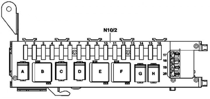
Fuse | Terminal | Connector | Wire color and section, mm2 | Purpose | Current strength (A) |
1 | 15R | Left seat adjustment: | 30 | ||
1, pin 5 | Black-yellow 2.5 | Driver's seat adjustment/memory control unit (N32/1) | |||
2 | 15R | Right seat adjustment: | 30 | ||
1, pin 6 | Black-pink 2.5 | Front passenger seat adjustment/memory control unit (N32/2) | |||
Semi-electronic front seat adjustment: | |||||
1 pin 6 | Black-yellow 2.5 | Driver adjustment relay (K5/1) /passenger (K5/2) seats | |||
3 | 30 | Tire inflation pressure control (TRS): | May 07 | ||
7, output 1 | Red-yellow 0.5 | TPC control unit (N88) | |||
TV ECE and USA: | |||||
9, output 1 | Red-yellow 0.75 | TV tuner (Europe, USA, Japan) (A2/42) | |||
TV Japan: | |||||
9, output 1 | Red-yellow 0.75 | TV tuner (A2/10) | |||
Models 203.7: | |||||
16, output 1 | Red-green 0.5 | Stationary heater radio remote control receiver (STH) (A6/1) | |||
17, output 1 | Red-green 0.75 | Rear interior lamp (Е15/3) | |||
Models 203.0 and 203.2 with Parktronic and rear interior light: | |||||
17, output 1 | Red-green 0.75 | Alarm display PTS (rear interior lamp) (A44/3) | |||
4 | 15R | 1, output 3 | Black-green 2.5 | Fuel pump (M3) | 15 |
5 | 15R | - | - | Backup relay 2 (N10/2kС) | 20 |
6 | 30 | 28, output 1 | - | - | 25 |
7 | 15R | - | - | Backup relay 1 (N10/2kD) | 20 |
8 | 30 | 23, pin 4 | Red-yellow 0.75 | Rear Window Antenna Amplifier Module 1 (A2/71) | 07-5 |
ATA with TS and IMS: | |||||
4, output 4 | Red-blue 0.5 | alarm siren (H3) | |||
4, output 5 | Red-white 0.5 | ATA tilt sensor (B33) | |||
9 | 30 | 22, pin 4 | Red-blue 2.5 | Overhead control panel control box (N70) | 25 |
10 | 15R | 20, pin 5 | Black 2.5 | Rear window heater (R1) | 40 |
11 | 15R | 20, output 3 | - | - | 20 |
12 | 15R | Models 203.2: | |||
20, output 2 | Black-green 1.5 | Internal socket (Х58/1) | 15 | ||
13 | 15R | 19, output 1 | Black-yellow 0.75 | Pneumatic pump for orthopedic seat (M40) | 5 |
Voice control system (VCS): | |||||
5, output 2 | Black-yellow 0.5 | Voice control unit (А35/11) | |||
Cell phone Motorola Star TAC, retrofit: | |||||
5, output 2 | Black-yellow 0.5 | D2B interface for portable mobile phone (A59/1) | |||
Models 203.0 and 203.2 with reading lights: | |||||
12, pin 5 | Black gray 0.5 | Rear Reading Light (Е15/3) | |||
Models 203.0 and 203.2 with reading lights and Parktronic: | |||||
12, pin 5 | Black gray 0.5 | Alarm display PTS (rear interior lamp) (A44/3) | |||
12, pin 5 | Black gray 0.5 | PTS control unit (N62) | |||
14 | 15R | 30, output 1 | Black-yellow 1.5 | - E/motor of a cleaner of back glass (М6/4) | 15 |
15 | - | - | - | - Filler relay, receiver polarity 1 (N10/2kG) | 10 |
16 | 30 | For VSC: | 20 | ||
5 output 1 | Red-violet 0.5 | Voice control unit (А35/11) | |||
For CTEL Motorola Star TAC, retrofit: | |||||
5 output 1 | Red-violet 0.75 | - D2B interface for mobile phone (A59/1) | |||
17 | 30 | S17 (external fuse) | Red-green 2.5 | For towbar: | 20 |
- hitch connector (N28/1) | |||||
18 | 30 | S18 (external fuse) | Red-yellow 2.5 | For towbar: | 20 |
- 13-pin hitch connector (X58) | |||||
19 | 30 | S19 (external fuse) | Red-white 1.5 | - Pneumatic pump for multi-contour seat (M40) | 20 |
20 | 30 | S20 (external fuse) | Red-blue 0.75 | To darken the rear window: | 7.5 |
- tinted rear window (K74) |
Relay | |
Location | Designation |
A | Fuel pump relay (N10/2kA) |
IN | Relay 2, terminal 15R (N10/2kV) |
WITH | Backup relay 2 (N10/2kС) |
D | Backup relay 1 (N10/2kD) |
E | Rear defroster relay (N10/2kЕ) |
F | Relay 1, terminal 15R (N10/2kF) |
G | Filler relay, polarity switch 1 (N10/2kG) |
H | Filler relay, polarity switch 2 (N10/2kN) |
Fuse box in the passenger compartment
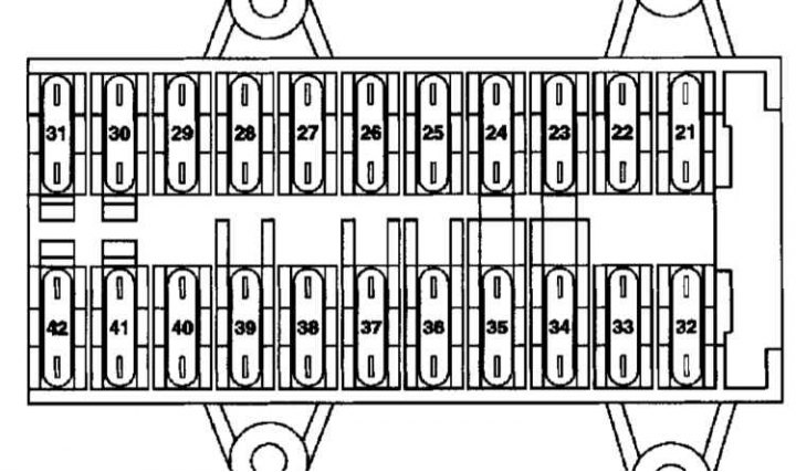
Fuse | Terminal | connector | Wire color and section, mm2 | Purpose | Current strength (A) |
21 | 30 | Х35/1 (left front door connector) | Red-white/2.5 | Left front door control unit (N69/1) | 30 |
22 | 30 | Х35/2 (right front door connector) | Red-grey/2.5 | Right front door control unit (N69/2) | 30 |
23 | 30 | - | - | cigarette lighter | 15 |
24 | 30 | - | - | Spare | - |
25 | 30 | 5, output 4 | Red-green/2.5 | Upper control panel control unit (N72/1) | 10 |
26 | 30 | 1, output 26 | Red-violet/4.0 | sound amplifier (A72/13) | 30 |
27 | 30 | 2, output 1 | Red-yellow/2.5 | Driver seat power control unit (with memory) (N32/1) | 30 |
28 | 30 | - | - | Spare | - |
29 | 30 | Х35/33 (frame-floor/emergency power connector) | Red-blue/2.5 | For Taxi: Dedicated bounce control module (SVMCM) (N26/9) | 30 |
30 | 30 | 1, output 3 | Red-green/4.0 | Heater air circulation unit (A32) | 40 |
31 | 30 | Ah, conclusion 9 | Red-violet/1.5 | EIS control unit (N73) | 20 |
32 | 30 | Х35/3 (left rear door connector) | Red-black/2.5 | Left rear door control unit | 30 |
33 | 30 | Х35/4 (right rear door connector) | Red-white/2.5 | Right rear door control unit | 30 |
34
| 30, 15 | - | Red-violet/1.5 | Connector sleeve glue 30 (Z4/3) | 07.5 |
Z4/3 (connector sleeve glue 30) | Red-violet/1.0 | For emergency call system (USA) and an additional cell phone: | |||
Cell phone and transceiver TELE AID D2B (A35/17) | |||||
Red-violet/1.5 | For built-in phone: | ||||
Cell phone and D2B transceiver (A35/13) | |||||
Red-violet/1.5 | For the TELE AID distress alert system: | ||||
Cell phone and transceiver TELE AID D2B (A35/17) | |||||
Red-violet/0.75 | For an additional cell phone: | ||||
Telephone interface (A34/4) | |||||
27 (connector sleeve glue 30) | Compensator CTEL (A28/3) | ||||
Red/0.5 | For an additional cell phone: | ||||
Telephone interface (A34/4) | |||||
Х39/37 (Portable phone connector) | Red-violet/1.0 | For Japanese models, 203.0 models and emergency call systems: | |||
Cell phone and transceiver TELE AID D2B (A35/17) | |||||
35 | 30 | 1, output 1 | Red-black/2.5 | For stationary heater (STH): | 30 |
Heater unit STH (A6) | |||||
36 | 30 | - | Red/1.5 | For government vehicles (STH): | 30 |
37 | 30 | 2, output 2 | Red-white/2.5 | Brake booster vacuum pump control unit (N65/3) | 25 |
38 | 30 | 2, output 1 | Red-green/2.5 | Right front seat power control unit (N32/2) | 30 |
39 | 30 | - | - | Spare | - |
40 | 30 | Х35/33 (frame-floor/emergency power socket) | Red-white/2.5 | For taxis and government vehicles: | 30 |
Dedicated bounce control module (SVMCM) (N26/9) | |||||
41 | 30 | 1, output 2 | Red-blue/0.5 | Upper control panel control unit (N72/1) | 07.5 |
1, pin 14 | Red-blue/0.75 2 | For automatic heater: | |||
Heater pushbutton control unit (N18) | |||||
For automatic A/C (AAS): | |||||
AAC push button control unit (N22) | |||||
For AAS system "comfort": | |||||
AAC push button control unit "comfort" (N22/7) | |||||
42 | 30 | 1, pin 5 | Red-yellow/0.5 | Dashboard (A1) | 07.5 |
Fuse and relay box in the engine compartment
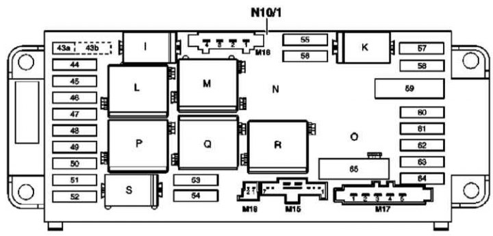
Relay | |
Location | Purpose |
i | Fanfare Klaxon Relay (N10/1kl) |
TO | Terminal 87 relay, chassis (N10/1kK) |
L | Speed relay (1 and 2) wipers (N10/1kL) |
M | Relay terminal 15R (N10/1kM) |
N | KSG pump control relay (N10/1kN) |
ABOUT | Secondary air pump relay (N10/1kO) |
R | Relay terminal 15 (N10/1kP) |
Q | Wiper On/Off Relay (N10/1kQ) |
R | Terminal 87 relay, motor (N10/1kR) |
S | Starter relay (N10/1kS) |
Fuse | Terminal | connector | Wire color and section, mm2 | Purpose | Current strength (A) |
43a | 15R | - | - | Fanfare Klaxon Relay (N10/1kl) | 15 |
43b | 30 | - | - | Fanfare Klaxon Relay (N10/1kl) | 15 |
44 | 15R | 23 | Black-yellow/0.5 | For the TELE AID distress alert system: | 5 |
TELE AID control unit (А35/8) | |||||
For built-in phone: | |||||
D2B interface (A59) | |||||
For an additional cell phone: | |||||
Telephone interface (A34/4) | |||||
For emergency call system (USA): | |||||
Connector ferrule 15R (Z3/12) | |||||
For emergency call system (Japan): | |||||
TELE AID control unit (А35/8) | |||||
45 | 15R | 12, pin 4 | Rose-black/0.75 | Protected by a fuse through the side airbag connector sleeve (Z3/31): | 07.5 |
SRS control unit (N2/7) | |||||
46 | 15 | - | - | Wiper On/Off Relay (N10/1kQ) | 40 |
47 | 15R | Backlight (in addition to the illumination of the deflectors): | 15 | ||
19, pin 6 | Black-yellow/0.75 | Glove box lights with sensor-switch (E13/2) | |||
19, pin 6 | Black-yellow/1.0 | Illuminated front ashtray/cigarette lighter | |||
48 | 15 | 3, output 1 | Black-green/1.0 | Brake booster vacuum pump control unit (N65/3) | 15 |
For engine 112: | |||||
17, pin 3 | Black-yellow/1.5 | Fuse-protected connector sleeve (Z3/29) 15 | |||
49 | 15 | 12, pin 3 | Black-red/0.5 | SRS control unit (N2/7) | 07.5 |
50 | 15 | 19, pin 4 | Black-green/0.5 | Light switch module (S1) | 5 |
14, output 1 | - | - | |||
51 | 15 | 19, pin 8 | Black-brown/0.5 | Dashboard (A1) | 07.5 |
2, output 6 | Black and white/0.75 | AAS (automatic A/C) with built-in auxiliary fan motor (M4/7) | |||
For AAS "comfort": | |||||
19, pin 8 | Black-brown/0.5 | Through the climate control sensor connector (Х85/9): | |||
AAC failure sensor (B31/1) | |||||
Solar radiation sensor AAC (4 pieces) (B32/2) | |||||
For all vehicles with xenon headlights: | |||||
24, output 1 | Black-pink/0.75 | Left block headlight (E1) | |||
Right block headlight (E2) | |||||
52 | 50 | 17, output 1 | Purple/2.5 | Starter (M1) | 15+ |
53 | 87 | 13, pin 3 | Violet-blue 0.5 | Rear SAM control box with relay and fuse box (N10/2) | 15 |
Engine 111: | |||||
2, output 9 | Red-blue 1.5 | ECM (N3/10) | 15 | ||
Engine 112: | |||||
2, output 9 | Red-blue 0.75 | ECM (N3/10) | 15 | ||
3, pin 8 | Red-blue 0.75 | Canister purge valve (Y58/1) | 15 | ||
17, output 2 | Red-blue 1.5 | Coupling connector glue 87M1e (Z7/35) | 15 | ||
Engine 611: | |||||
2, output 9 | Red-blue 2.5 | Contact ignition system control unit (CDI) (N3/9) | 25 | ||
3, pin 8 | Red-blue 2.5 | CDI control unit (N3/9) | 25 | ||
54 | 87 | Diesel engines: | |||
2, output 2 | Black-red 2.5 | CDI control unit (N3/9) | 07.5 | ||
17, pin 4 | Black-red 1.0 | intake manifold heater (R8) | 07.5 | ||
Petrol engines: | |||||
2, output 2 | Black-red 2.5 | Coupling connector glue 87M1e (Z7/36) | 15 | ||
17, pin 4 (only 112 engines) | Red-green 1.0 | (only 112 engines) | |||
Coupling connector glue 87M1e (Z7/36) | 07.5 | ||||
55 | 87 | 7, output 5 | Red-green 0.5 | Steering wheel sensor (N49) | 07.5 |
DTR: | |||||
21, output 1 | Red-blue 0.75 | DTR control unit (N63/1) | |||
AT: | |||||
9, output 1 | Red-white 0.75 | ETC control unit (N15/3) | |||
9, output 3 | Red-blue 0.75 | Selector lever electronic control unit (N15/5) | |||
Automated checkpoint (Sequentronic): | |||||
9, output 1 | Red-white 1.0 | Sequentronic control unit (N15/6) | |||
9, output 3 | Red-blue 0.75 | Transmission Position Sensor (S16/10) | |||
56 | 87 | 7, output 3 | Red-blue 0.75 | ESP and BAS control unit (N47-5) | 5 |
7, output 4 | Red-yellow 0.5 | Brake light switch (S9/10) | |||
57 | 30z | 19, output 1 | Red-black 0.5 | Steering wheel sensor (N49) | 5 |
19, output 1 | Red-blue 0.5 | Electronic ignition control unit / sensor-switch opening the starter circuit (N73) | |||
Engine 112: | |||||
2, output 4 | Red 0.75 | ECM (N3/10) | |||
58 | 30 | Automated checkpoint (Sequentronic): | |||
9, output 4 | Black-blue 0.5 | Sequentronic control unit (N15/6) | 40 | ||
59 | 30 | 8, output 2 | Red 4.0 | ESP and BAS control unit (N47-5) | 50 |
60 | 30 | 8, output 1 | Red 2.5 | ESP and BAS control unit (N47-5) | 40 |
61 | 30 | Automated checkpoint (Sequentronic): | |||
9, pin 6 | Black-green 0.5 | Sequentronic control unit (N15/6) | 15 | ||
62 | 30 | 2, pin 11 | Red-green 0.75 | DLC connector (Х11/4) | 5 |
19, output 2 | Red-yellow 0.5 | Lamp switching module (S1) | |||
7, output 7 | Rose green 0.5 | Brake light switch (S9/1) | |||
63 | 30 | 19, pin 5 | Red-green 0.5 | Lamp switching module (S1) | 5 |
64 | 30 | Radio: | |||
11, output 2 | Red-blue 2.5 | Radio (A2) | 10 | ||
COMAND version: | |||||
11, output 2 | Red-blue 2.5 | Display and function control unit COMAND (А40/3n1) | |||
65 | 15 | Exhaust air injection: | |||
17, pin 5 | Red-white 4.0 | Electric air pump (M33) | 40 |
Tightening force of threaded connections, Nm
Fastener tightening torques are also given in the text of the Chapter and in some illustrations *.
* The tightening torques shown in bold type must be strictly adhered to; Efforts not in bold type are indicative only.