
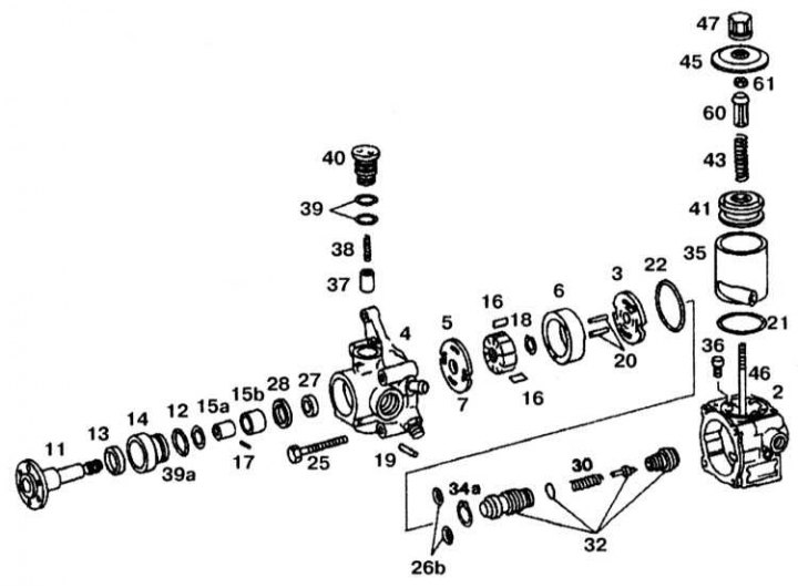
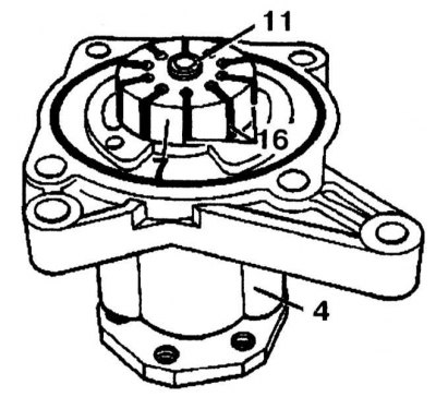
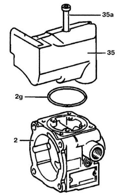
Power steering pump (disassembled)
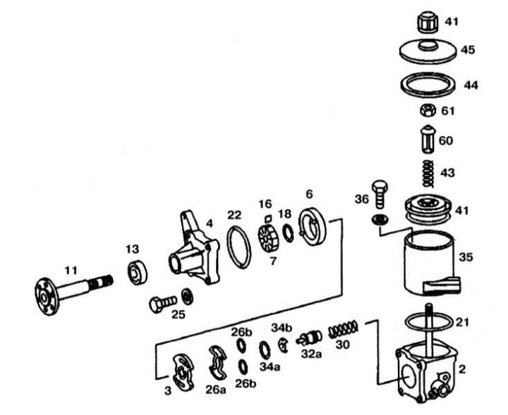
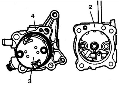
2 - Pump casing; 3 - Plate; 4 - Flange; 6 - Cam insert; 7 - Rotor; 11 - Drive shaft; 13 - Oil seal; 16 - Blade; 18, 34a, 34b - Retaining rings; 21, 22, 26a, 26b, 44 - O-rings; 30, 43 - Springs; 32 - Flow control valve; 35 - Tank; 36 - Bolt; 41 - Filter; 45 - Cover; 47 - Ventilation cover; 60 - Plastic sleeve; 61 - Nut
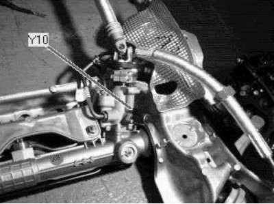
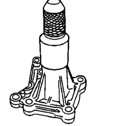
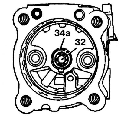
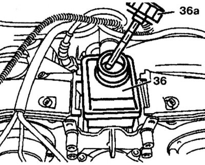
Valve P speed sensitive power steering (on the power steering pump, on the left in the engine compartment)
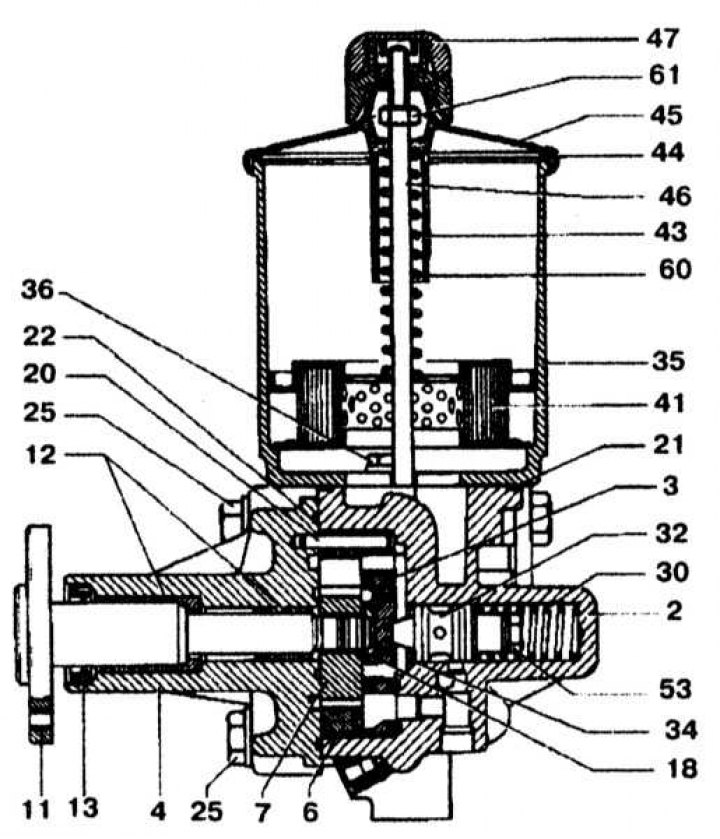
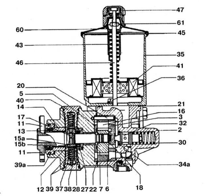
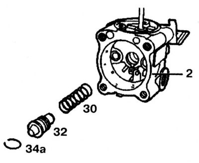
Power steering pump (complete)
Disassembly
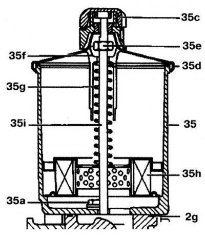
1. Unscrew the ventilation cover 47 and remove the cover 45.
2. Unscrew the nut 61 from the support bolt, remove the plastic sleeve 60, the spring 43 and the filter 41.
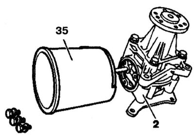
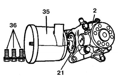
3. On Vickers/LUK pumps, reservoir 35 can be removed. Replace O-ring. On ZF pumps, molded together with casing 2.
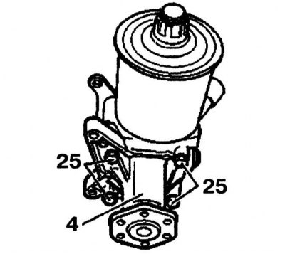
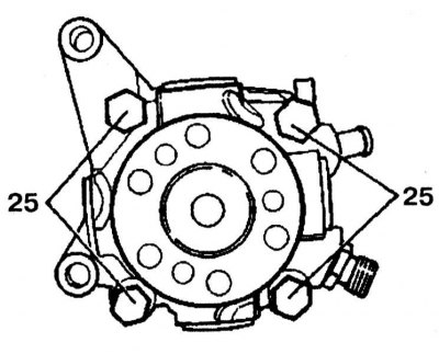
4. Unscrew the bolts 25 and remove the flange 4. Check the lower part of the flange 4 for damage and wear.
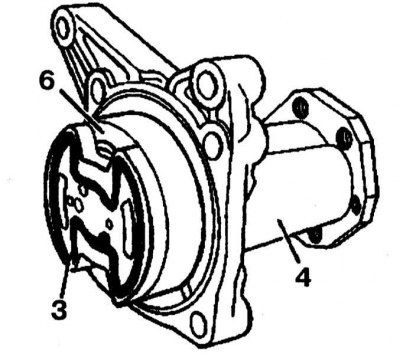
5. Remove pressure plate 3 and cam insert 6.
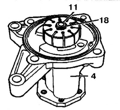
6. Remove circlip 18 from drive shaft 11. Replace circlip.

7. Remove the rotor 7 with a plastic hammer from the drive shaft 11 together with the blades 16 (10 pieces).
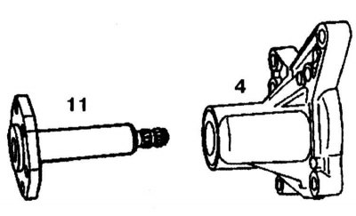
8. Remove drive shaft 11 from flange 4.
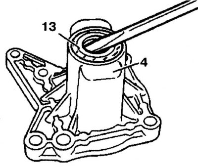
9. Using a screwdriver, press out the radial seal 13 from the flange 4.
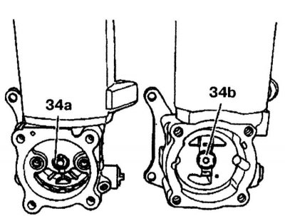
34a - Vickers / LUK pump
34b - ZF pump
10. Remove retaining ring 34a or 34b.
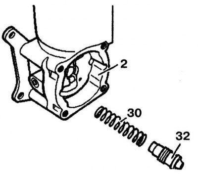
11. Remove fluid flow control valve 32 and spring 30 from pump body 2.
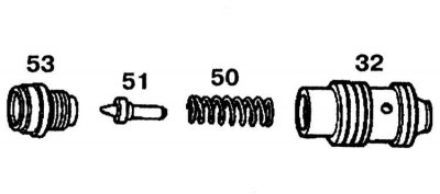
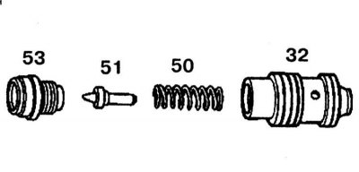
12. Place fluid flow control valve 32 in a vise and unscrew valve 53 from overpressure valve.
13. Remove sealing cone 51 and spring 50. Check fluid flow control valve contact surfaces 32 and pump housing bore for wear or damage. If wear on the sealing surfaces is determined, the pump must be replaced.
14. Check both sealing cones. Replace worn cone.
Assembly
1. Lubricate all parts with oil before starting assembly. Replace all o-rings. If a new fluid flow control valve 32 is installed, pay attention to the correct opening pressure of the overpressure valve.
2. Assemble fluid flow control valve 32 in an E vise and tighten valve 53.
3. Insert spring 30 and fluid flow control valve 32 into pump body 2.
4. Install circlip 34a or 34b.
5. Install a new oil seal into the flange using a punch.
6. Further installation is carried out in the reverse order of removal.
7. After assembling the pump, check that the pump is working properly and that there are no fluid leaks. If necessary, check the operating pressure of the pump.
Power steering pump type «Tandem» - models 62, 162
Power steering pump type «Tandem» disassembled
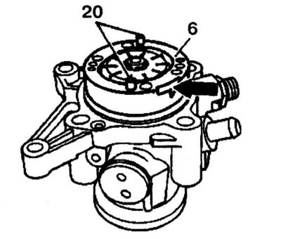
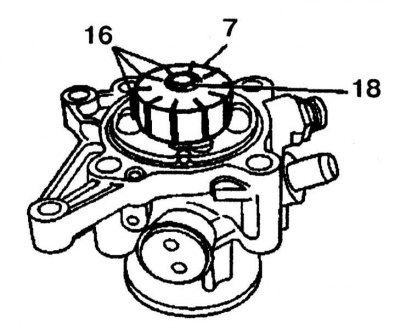
2 - Pump casing; 3 - Pressure plate; 4, 14 - Flanges; 5, 12 - Thrust pads; 6 - Cam insert; 7 - Rotor; 11 - Drive shaft; 13, 27 - Radial oil seals; 15a - Eccentric; 15b - Sleeve; 16 - Blade; 17, 19, 20 - Fingers; 18 - Retaining ring; 21, 22, 26b, 39, 39a - O-rings; 25, 36 - Bolts; 27 - Oil seal; 28 - Gasket; 30, 38, 43 - Springs; 32 - Fluid flow control valve; 35 - Reservoir; 37 - Piston; 40 - Screw plug; 41 - Filter; 45 - Cover; 46 - Support bolt; 47 - Ventilation cover; 60 - Plastic sleeve; 61 - Nut
Power steering pump type «Tandem» - assembled
Power steering pump type «Tandem» - models 62, 162 shown in the illustrations.
Disassembly
1. Unscrew the ventilation cover 47 and remove the cover 45.
2. Unscrew the nut 61 of the support bolt 46. Remove the plastic sleeve 60, the spring 43 and the filter 41.
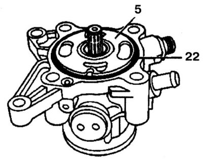
3. Unscrew the bolts 36 of the pump housing 2. Remove the tank 35 and the sealing ring 21.
4. Turn away bolts 25 and remove a flange. Check the flange contact surface for wear and damage.
5. Remove pressure plate 3.
6. Remove the cam insert 6. Check the pressure plate contact surface as well as the sliding surfaces of the vanes on the cam insert 6 for wear and tear.
7. Remove retaining ring 18 from drive shaft. Replace retaining ring.
8. Remove the rotor 7 from the drive shaft 11 using a mallet and remove the blades 16 (10 pieces). Check the blades 16 in the grooves of the rotor 7; they should slide in the rotor easily.
9. Remove thrust pad 5.
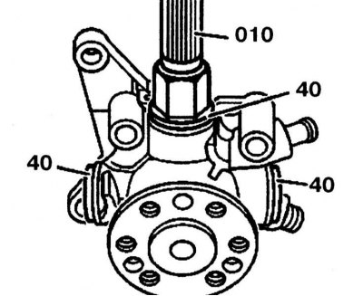
10. Unscrew all four nuts 40 from the pump housing using the 010 wrench.
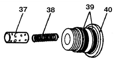
11. Check seals 39 and replace if necessary. Remove piston 37 and spring 38 from plug 40. Check piston and piston guide for signs of wear and damage. If the piston moves in the guide with noticeable difficulty, the plug must be replaced.
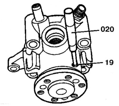
12. Knock out pin 19 from the pump housing using a punch.
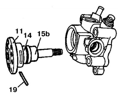
13. Remove drive shaft 11 together with sleeve 15b and flange 14 from the pump casing.
14. Remove bushing 15b and inspect it.
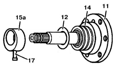
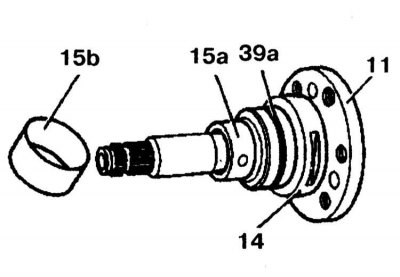
15. Knock out the pin 17 with a drift and remove the eccentric 15a. Remove the thrust pad 12 and check its condition. Remove flange 14 from drive shaft 11.
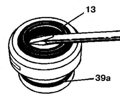
16. Use a screwdriver to remove the radial seal 13 from the flange. Replace O-ring 39a.
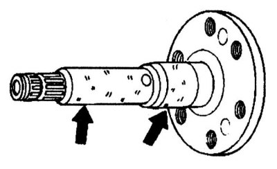
17. Check bearing surfaces (arrows) on the drive shaft for wear or nicks.
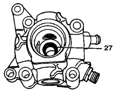
18. Check the radial stuffing box 27 in the pump casing. If fluid is found on the pump, the probable cause is a leaking stuffing box 27.
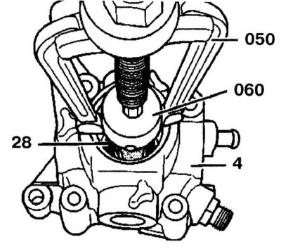
19. Remove the radial oil seal and gasket 28 using a puller. Check the bronze bushing in housing 4 for signs of wear and damage and replace if necessary.
20. Remove retaining ring 34a. When removing the retaining ring, make sure that the pump housing is not damaged.
21. Remove fluid flow control valve 32 and spring 30 from pump body 2.
22. Place fluid flow control valve 32 in a vise and unscrew valve 53 from overpressure valve.
23. Remove sealing cone 51 and spring 50. Check fluid flow control valve contact surfaces 32 and pump housing bore for wear or damage. If wear on the sealing surfaces is determined, the pump must be replaced.
24. Check both sealing cones. Replace worn cone.
Assembly
1. Assembly is carried out in the reverse order of removal.
2. After assembling the pump, check that the pump is working properly and that there are no fluid leaks. If necessary, check the operating pressure of the pump.
Power steering pump type «Tandem»
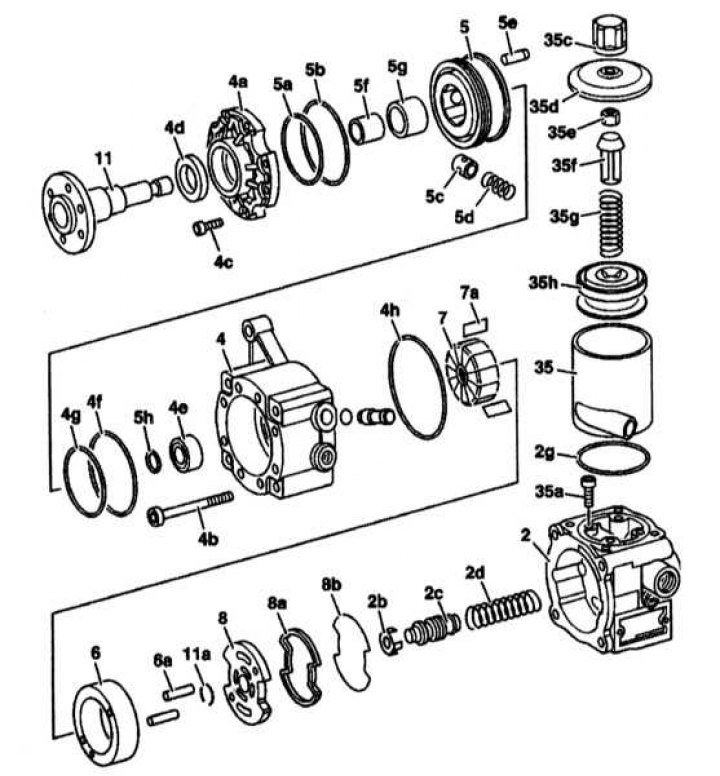
2 - Pump casing; 2b, 2c - Fluid flow control valve; 2d, 5d, 35g - Springs; 2g, 4f, 4h, 5a, 5b, 35a - O-rings; 4 - Pump body; 4a - Flange cover; 4b, 4c - Bolts; 4d, 4e - Radial seals; 5 - Piston support ring; 5c - Piston; 5f - Sleeve; 5g - Bearing; 6 - Cam insert; 6a. - Fingers; 7 - Rotor; 7a - Blades; 8 - Pressure plate; 8a - Oil seal; 8b - Gasket; 11 - Drive shaft; 11 a - Retaining ring; 35 - Tank; 35s - Ventilation cover; 35d - Cover; 35e - Nut; 35f - Plastic sleeve; 35g - Spring; 35h - Filter
1. Power steering pump type «Tandem» shown in the illustration.
2. Remove sealing cone 51 and spring 50.
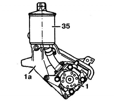
Attention! On some models, the tank 35 can be mounted on a bracket 1a, which in turn is screwed to the pump 1.
Disassembly
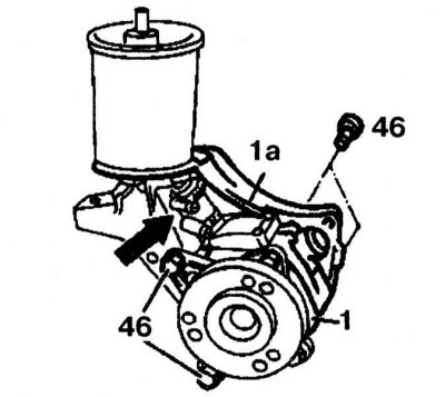
1. Loosen the clamp, disconnect the tube (arrow) and fasten it to the side. Unscrew bolts 46 and remove pump 1 from bracket 1a.
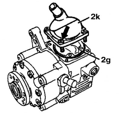
2. Remove the bolts (4 pieces). Remove cover 2k, check O-ring 2g, replace if necessary.
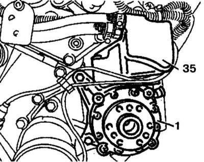
3. On some models, pump 1 has an expansion tank to adjust the oil in tank 35 located between the thermostat and intake manifold.
4. Oil level indicator 36a with marks «min» And «max» to check the oil level is located on the cover of the expansion tank 36.
5. Turn away four bolts 35a of fastening of the tank 35 and remove it. Check O-ring 2g, replace if necessary.
6. Unscrew the vent cap 35c and remove the cap 35d.
7. Remove nut 35e from support bolt 35i. Remove plastic sleeve 35f, spring 35g and filter 35h.
8. Remove screws 4b on flange 4 and remove pump housing 2.
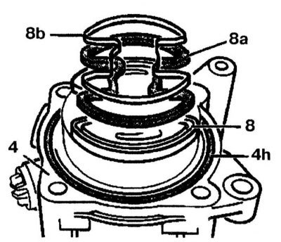
9. Remove O-ring 4h from flange 4, check and replace if necessary. Remove pressure plate 8. Check oil seal 8a and cone gasket 8b and replace oil seal if necessary.
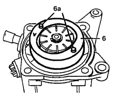
10. Remove the cam insert 6 and fingers 6a. Check the pressure plate surface as well as the sliding surface of the paddles on the cam insert for wear or damage.
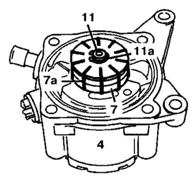
11. Remove the circlip 11a from the drive shaft 11. Replace the circlip.
12. Remove the rotor 7 from the drive shaft 11 with a plastic hammer and remove all the blades 7a (10 pieces).
13. On ZF pump: remove drive shaft 11 from flange 4. On Vickers/LUK pumps: first remove 10 vanes and then remove drive shaft with flange cover.
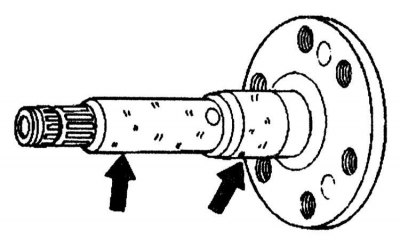
14. Check the drive shaft for nicks and wear on the bearing surfaces (arrow). If necessary, replace it.
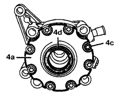
15. Remove bolts 4c (8 pieces) and remove the flange cover 4a. Check radial oil seal 4d and replace if necessary.
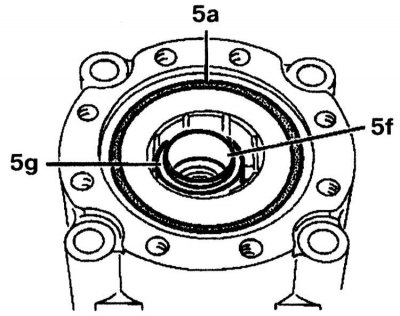
16. Replace O-ring 5a. On a ZF pump: remove bushing 5f and bearing 5g. On Vickers/LUK pumps: Remove circlip from drive shaft, remove spacer and bushing 5f from bearing 5g.
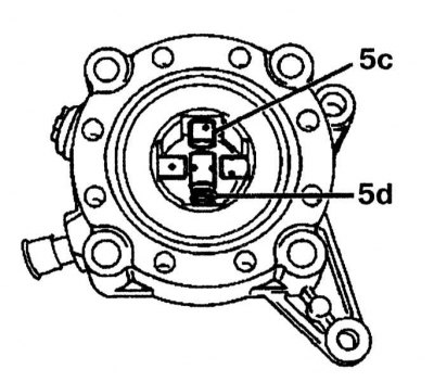
17. Remove piston 5c and spring 5d. Check piston and spring for wear and damage.
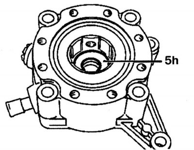
18. Remove gasket 5h from the ZF pump housing.
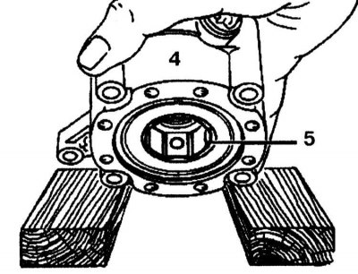
19. Fasten flange 4 between two wooden blocks so that ring 5 can be removed.
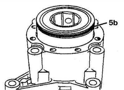
20. Replace O-ring 5b.
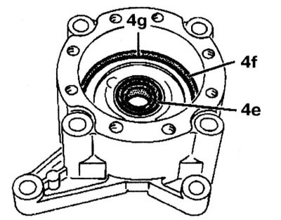
21. Replace O-ring 4f and V-ring 4g in the pump housing. Check radial oil seal 4e and replace if necessary.
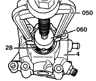
22. Remove radial oil seal 4e using a puller. Check the bronze bushing in body 4 for damage and wear and replace if necessary.
23. Remove fluid flow control valve 2c and spring 2j from pump body 2.
24. Fix the fluid flow control valve 2c in a vise and unscrew the valve 2e from the overpressure valve.
25. Remove sealing cone 2f and spring 2d. Check the contact surfaces of the fluid flow control valve 2c and the bore in the pump housing for wear or damage. If wear on the sealing surfaces is determined, the pump must be replaced.
26. Check both sealing cones. Replace worn cone.
Assembly
1. Assembly is carried out in the reverse order of removal.
2. After assembling the pump, check that it works properly and that there is no liquid leakage. If necessary, check the operating pressure of the pump.