



General view of the manual transmission
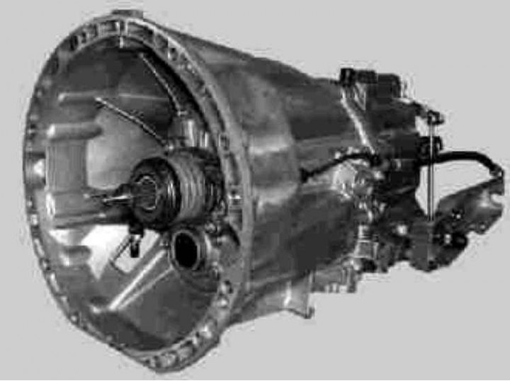
716.6 belongs to the class of fully synchronized 2-shaft 6-speed gearboxes with one reverse gear, which are widely used in rear-wheel drive passenger cars (both petrol and diesel).
Four versions of 6-speed gearboxes are produced, designed for torque from 250 to 400 Nm.
6-speed manual transmission 716.6
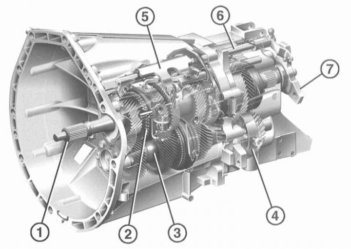
1 - Primary shaft of the gearbox; 2 - Synchronizing ring 5/6 gears; 3 - Shaft; 4 - Reverse bearing shell; 5 - Shift cam; 6 - Switching axis; 7 - Flange connecting to the cardan shaft
Elements of manual transmission
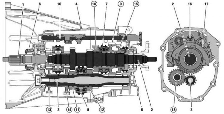
1 - Input shaft; 2 - Main shaft; 3 - Intermediate shaft; 4 - Front crankcase; 5 - Rear crankcase; 6 - Clutch release device; 7 - Multi-cone synchronizer 1/2 shift; 8 - Multi-cone synchronizer 3/4 shift; 9 - 1st gear pinion; 10 - 2nd gear pinion; 11 - 3rd gear pinion; 12 - 4th gear pinion; 13 - 5th gear pinion; 14 - 6th gear pinion; 15 - Reverse gear; 16 - Central shift rod; 17 - Internal switching module; 18 - Reverse intermediate gear
Proper use of the 6th gear allows achieving significant savings in fuel consumption by reducing the engine operating speed. Due to design features.
6-speed transmissions are heavier than 5-speed transmissions.
The gearbox receives torque from the engine via a conventional dry clutch equipped with an automatic wear compensator. The gearbox has a sealed design and is filled with transmission oil that does not require replacement.
The precision and ease of short-throw transmission shifts are achieved by the following design features:
- Rod-cable design of the shift drive;
- Application of a central shift rod secured in needle bearings;
- Using multi-cone synchronizers for shifting 1st, 2nd, 3rd and 4th gears;
- Fully synchronized reverse gear.
The gearbox assemblies with shafts are placed between two bearing planes. The third bearing plane used in earlier 5-speed boxes is eliminated in this design.
The two-section split crankcase is made of light alloy and sealed with a special liquid compound.
The input shaft (1) is fixed in the flywheel by means of a guide bearing, and in the transmission housing by means of a ball bearing with a deep groove. The main (2) and input (1) shafts are connected to each other in the common plane of the transmission housing and are fixed by means of ball bearings with a deep groove.
The intermediate shaft (3) has a lightweight hollow design and is secured in a roller clutch and a ball bearing with a deep groove.
Due to the minimal manufacturing tolerances of the half-crankcases and gears, as well as the use of roller clutches, there is no need to adjust the axial clearances of the shafts.
The movements of the gearshift lever are transmitted via rods to the gearbox. The gearbox can be removed without removing the engine. It is necessary to remove the gearbox when removing the clutch, when replacing the gearbox or repairing it. It is not recommended to repair the gearbox at home. The control of the manual transmission is described in Chapter User manual.