
Removing
Removal and installation of M120.980 engines
1. Raise the hood.
2. Disconnect the negative cable from the battery.
3. Remove the air filter along with the air flow meter.
4. Remove the bottom motor guard.
5. Remove the radiator.
6. Turn away oil pipelines of transmission liquid АТ.
7. Attach the protective plate to the air conditioner condenser.
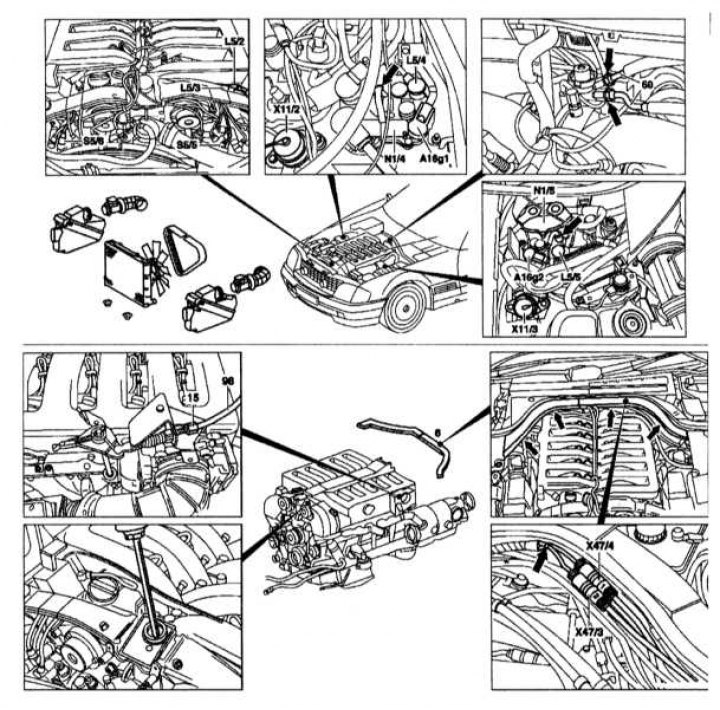
8. Disconnect the drive cable from the hood lock on the left.
9. Disconnect branch pipes of system of cooling in a back part of a head of the block of cylinders.
10. Remove the fan clutch together with the fan.
11. Remove the alternator drive belt.
12. Disconnect the fuel lines (60).
13. Remove the cover (6) wires.
14. Disconnect the engine wiring (all connectors).
15. Remove the drive cable (98) (throttle control).
16. Turn away vacuum tubes from the vacuum amplifier on the inlet pipeline.
17. Remove the fluid from the power steering pump reservoir.
Removal and installation of engines M120.980
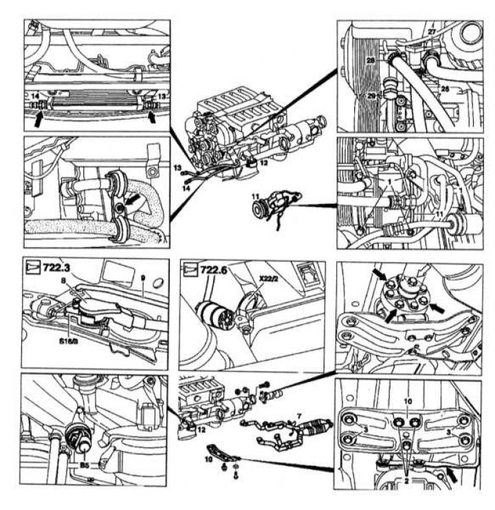
1. Disconnect the pipes from the power steering pump (26), (27), (28) And (29).
2. Remove the piping bracket.
3. Unscrew the pipelines (13) And (14) from the oil cooler and the right cooling tube (13) from the radiator cross member.
4. Remove the oil pressure sensor (AT 5).
5. Disconnect the A/C compressor (11) with tubing attached.
6. Remove the exhaust pipe (7) assembled.
7. Drain the coolant.
Removal and installation of engines M120.980
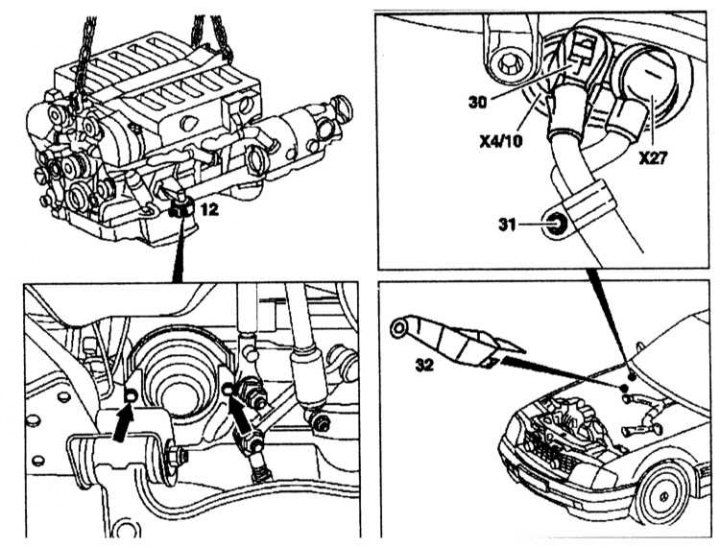
1. Unscrew the shield (32) starter wiring.
2. Disconnect the circuit wire (30) from the starter.
3. Remove the flexible joint of the cardan shaft.
4. Unscrew the connection wire on «mass» gearboxes.
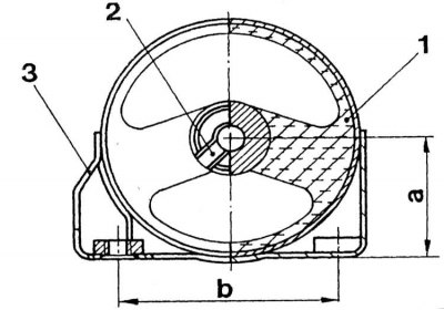
The design of the rear suspension support of the power unit
1 - Elastic element
2 - Torsion limiter
3 - Bracket
1. Remove the rear bracket (10) without engine mount.
2. Disconnect the shift lever (9) from the gearbox.
3. Disconnect the electrical wiring from the gearbox.
Removal and installation of engines M120.980

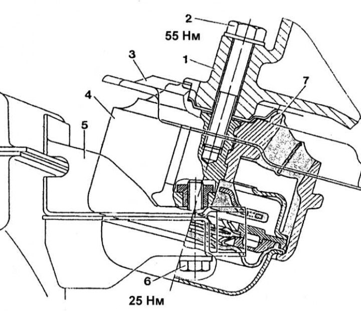
The design of the front support suspension of the power unit
1 - Bracket; 2 - Bolt М10ґ55; 3 - Thermal protection screen; 4 - Support; 5 - Holder; 6 - Bolt М8ґ42; 7 - Torsion limiter
1. Remove the front engine mount (12) at both sides. The design of the front support is shown in Ref. illustrations.
2. Attach the lift to the engine.
3. Raise the engine and transmission until the compressor (11) cannot be removed from the bracket on the engine with pipes attached.
4. Raise the engine and remove it.
Installation
Installation is made in an order, the return to removal.