



Connecting elements of the heating control relay N 14
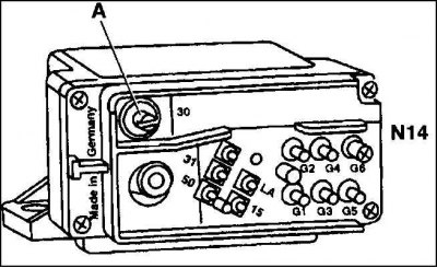
30 – terminal 30, continuous load current; 31 – terminal 31, body (–); 50 – terminal 50, voltage when pressing the starter; LA – terminal of the heating control lamp; 15 – terminal 15, voltage with ignition on; G1–G5 = connection of glow plugs 1–5
1. Connect a voltmeter between terminal 30 (A) of the heater control relay plug and the housing. The meter should indicate battery voltage (about 12 V).
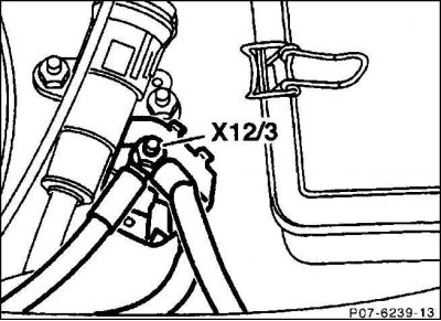
2. Otherwise, check for a break in the red wire going from the junction block (X12/3) to the heating control relay.
3. Turn the ignition key to warm up and connect the voltmeter to the connector 1 (terminal 15) of the 6-pin plug and the housing. Specified value: battery voltage (about 12 V). If there is no voltage, then check for a break in the black/red wire from fuse 23 (unprotected side) to the plug, pin 1.
4. Connect the voltmeter to connector 1 (+, terminal 15) and connector 4 (–, terminal 31). Specified value: battery voltage (about 12 V). Otherwise, check the brown wire from connector 4 to the body for a break.