
M119.97 series engine with mounting bearing
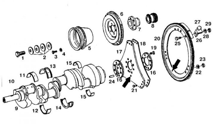
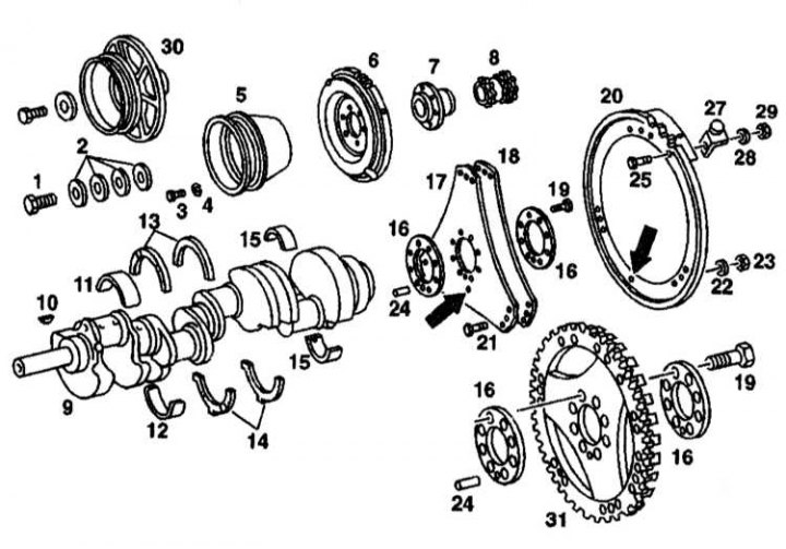
Installation details of the crankshaft with the installation bearing
1, 3, 19, 21, 25 - Bolt; 2, 28 - Gaskets; 4, 22 - Engraver; 5 - Crankshaft pulley; 6 - Torsional vibration damper; 7 - Hub; 8 - Crankshaft sprocket; 9 - Crankshaft; 10 - Key; 11 - Upper main bearing shell; 12 - Lower main bearing shell; 13 - Upper mounting bearing (insert) with oil hole; 14 - Lower installation bearing (insert); 15 - The upper shell of the connecting rod bearing; 16 - Disc 4.5 mm; 17 - Leading disk 1.5 mm thick and 296 mm in diameter; 18 - Leading disk 1 mm thick and 287 mm in diameter; 20 - Flywheel ring gear; 23, 29 - Nuts; 24 - Finger; 26 - Bracket; 27 - Magnet
The installation details of the crankshaft with the installation bearing are shown in Ref. illustrations. Dimensional characteristics of the crankshaft are given in Specifications.
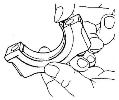
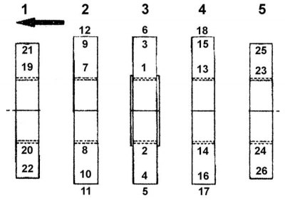
Designation of the main bearing shells and installation of the crankshaft
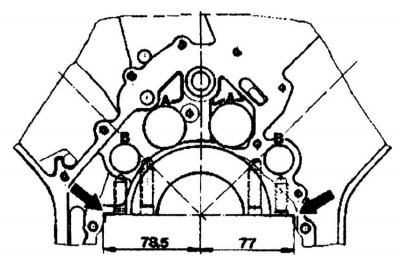
1. Establish covers of radical bearings, observing designation and since the first. The mounting surface of the cylinder block is asymmetrical, the crankshaft covers can only be installed in one position.
2. Lubricate the threaded part and the contact surfaces of the nuts and tighten them to a torque of 50 Nm.
3. Lubricate the threaded part and the contact surfaces of the M10x40 side bolts, install them with gaskets and tighten with a torque of 50 Nm.
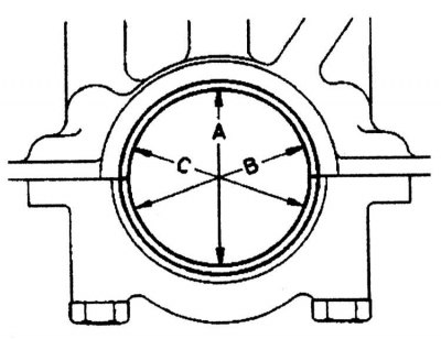
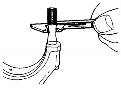
4. Measure the main bearing bore in directions A, B and C at two levels (taper). If the hole diameter is larger than allowed or has a taper, install a plate on the mating surface of the cover (Max. up to 0.02 mm).
5. Insert the lower loose leaf and establish a cover of the radical bearing. Tighten the nuts and side bolts to 50 Nm.
6. Measure the hole diameters and write them down.
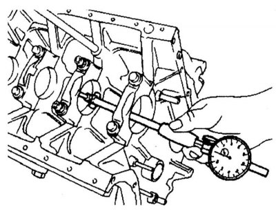
7. Measure the diameters of the main journals and determine the radial clearance of the crankshaft bearings. Achieving the required radial clearance can be achieved by replacing the bushings.

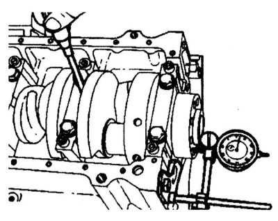
8. Measure the width of the main bearing journal. Determine the axial clearance of the crankshaft. Repair inserts are supplied oversized.
9. Lubricate the liners and the crankshaft with engine oil and install the crankshaft.
Attention! Inserts with oil channels are installed from above!
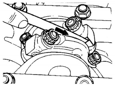
10. Tighten the main bearing caps in the order shown in the illustration.
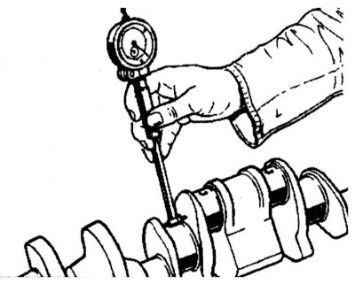
11. Measure the end play of the crankshaft.
12. Turn a cranked shaft by hand and check up ease of its rotation.
Designation of connecting rod bearing shells and their installation
1. Check connecting rod bolts.
2. Insert the connecting rod bearing shells, install the connecting rod caps with shells and tighten the nuts or bolts to 35 Nm.
3. Measure the diameter of the crankpin hole and write it down.
4. Measure the width of the connecting rod journal and determine the radial clearance of the connecting rod bearings.
5. Lubricate liners, crankshaft, pistons and cylinders with impellent oil. Install pistons and connecting rods.
6. Tighten the nuts and bolts of the connecting rod caps. 7. Measure the end play of the connecting rods.
M119.97/98 series motors with thrust half rings
Installation details of the crankshaft with thrust half rings
1, 3, 19, 21, 25 - Bolts; 2, 4, 22, 28 - Gaskets; 5 - Crankshaft pulley; 6 - Torsional vibration damper; 7 - Hub; 8 - Crankshaft sprocket; 9 - Crankshaft; 10 - Key; 11 - The upper loose leaf of the main bearing of the crankshaft; 12 - The lower loose leaf of the crankshaft main bearing; 13 - Upper thrust half rings; 14 - Lower thrust half rings; 15 - Connecting rod bearings; 16 - Disc 4.5 mm thick; 17 - Leading disk 1.5 mm thick with a diameter of 296 mm; 18 - Leading disk 1 mm thick and 287 mm in diameter; 20 - Flywheel ring gear; 23, 28 - Nuts; 24 - Finger; 26 - Bracket; 27 - Magnet; 29 - Nut M5; 30 - Vibration damper with pulley; 31 - Flywheel ring gear (only on models with Motronic control system)
Dimensional characteristics of the crankshaft are given in Specifications.