



Voltage measurement
The presence of voltage in a circuit can be detected using a test lamp or voltage indicator. However, such a device only detects the presence of voltage, but does not measure it. To measure voltage, it is necessary to use a voltmeter, which is always an integral part of a multifunctional measuring device.
First of all, you need to set the scale of the device depending on the expected values of the measured voltage. Usually, the voltage does not exceed 14 V. The exception is the ignition system, in which the voltage can reach up to 30,000 V. Such voltage can only be measured with a special measuring device or using an oscilloscope.
While a voltmeter only requires switching on when used in specially designed measuring devices, when using a multi-function meter, a number of steps must be taken. First, the range switch must be set to the DC position (d.C) unlike the AC mode (aC). Then you need to select the desired scale. Since there are no voltages higher than 14 V on the car, except for the ignition voltage, the upper limit of voltage measurements should be slightly higher (approximately 15-20 V). If it is known in advance that the measured voltage will be significantly lower, for example, in the 2 V range, the voltage measurement range can be switched to a lower one to achieve higher measurement accuracy. If the measured voltage turns out to be higher than the selected measurement range, the device may fail.
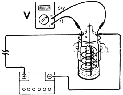
Connect the meter leads parallel to the element. The red lead is connected to the positive terminal, while the black lead is connected to the ground terminal or to the engine body (ground), such as the engine block.
Check: If the engine does not start due to the starter turning weakly, it is necessary to measure the voltage of the battery with the starter running. To do this, connect the red lead (+) of the voltmeter to the positive terminal of the battery, and the black lead (-) to the grounded terminal of the battery. Then ask an assistant to turn on the starter and read the voltage on the scale of the device. If the voltage is below 7 V, the battery should be checked and possibly recharged before turning the starter again.
Measuring current
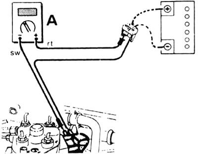
To measure the current in an electric circuit, it is necessary to break it and insert a measuring device (ammeter) into the break in the circuit. In this case, the connector is removed and the red wire (+) of the ammeter is connected to the current-carrying wire (terminal 30, terminal 15). The black wire (-) is connected to the contact to which the broken wire was previously connected. The ground contacts between the electrical consumer and the connector must be connected to the additional wire.
Example: "Self-discharge of the battery".
Note: Never measure the current in the wire going to the starter (approximately 150 A) or to the starter connectors in a diesel engine (approximately 60 A), using a regular ammeter. Large currents can damage the measuring device. In a repair shop, an ammeter with current pliers is used, which grasp the current-carrying wire and measure the strength of this current by induction.
Measuring resistance
Before you begin the procedure for measuring the resistance of an electrical circuit, you must make sure that there is no voltage at the resistance measurement points. Therefore, always first disconnect all electrical connectors, turn off the ignition, disconnect the wire or block connected to the battery, or disconnect the battery itself. Otherwise, the measuring device may be damaged.
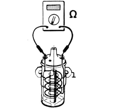
The ohmmeter is connected to two connections of an electrical element or to two ends of an electrical wire. It does not matter which wire (+/-) of the ohmmeter is connected to one or another contact of the device.
Resistance measurement on a vehicle is carried out mainly in two areas:
1. Checking the resistance of a circuit with a constant or variable level of values (resistance). Example: checking the resistance of a temperature sensor by disconnecting the connector from this sensor and connecting an ohmmeter to the gap between the connector and the sensor. Turn on the ohmmeter to the scale within which the measurement of the expected resistance values will be carried out, and compare the obtained value with the values given in the reference table.
2. "Continuity" test of an electrical wire, switch or heater filament. This test determines whether there is a break in the car wire and whether the connected electrical devices can operate. If the resistance of the circuit is 0 ohms, the "continuity" of the circuit is maintained and, therefore, the device or wire being measured is in good condition. If there is a break in the circuit, the measuring device will show infinite resistance.
Article obtained from this portal (mercedesman)