
The layout of the components of control systems. Models C240 and C320
1 - Connector for measuring fuel pressure; 2 - Fuel line; 3 - Fuel tank; 4 - Coal adsorber; 5 - Fuel filter with built-in pressure regulator; 6 - Fuel supply line to the engine; 7 - Adsorber purge control valve
Gasoline engines
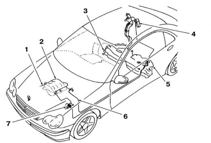
The composition of the fuel system includes: installed at the rear of the car (under the rear seat cushion) fuel tank with activated charcoal adsorber, fuel lines, electric fuel pump, and electronic sequential injection system controlled by the control unit. The functional diagram of the control system and the location of the sensors are shown in the accompanying illustrations.
The fuel reserve is shown to the driver on the instrument panel. In a gasoline engine, gasoline vapors are collected in an adsorber and fed into the combustion chambers of the engine.
Driving style has a significant impact on fuel consumption. Below are a few tips for sensible use of the gas pedal.
- Drive away immediately after starting the engine, even if it is in the cold.
- When the vehicle is stopped for more than 40 seconds, turn off the engine.
- Always drive in the highest possible gear.
- When driving long distances, maintain a steady speed whenever possible. Avoid driving at high speeds. Drive carefully. Don't slow down unnecessarily.
- Do not carry excess cargo on the vehicle. If the roof rack is not in use, remove it from the roof.
- Check tire pressure. Avoid excessive pressure reduction.
Diesel engines
The composition of the fuel system includes: installed at the rear of the car (under the rear seat cushion) fuel tank, fuel filter, injectors, fuel pipes and hoses, a fuel gauge located inside the tank and an electronic engine control unit.
Fuel is supplied by a special pump through the filter. Dirt and water contained in the fuel settles in the filter.
The engine is controlled by an electronic system similar to that of a gasoline engine. The system controls the operation of the engine by analyzing information from a large number of sensors.
Diesel models do not have an accelerator cable. Instead, a pedal position sensor is installed on the pedal.
There is no fuel cut-off valve when the ignition is turned off. In order to turn off the engine when the ignition is turned off, the engine control unit sends a signal to the injection pump control unit, which, in turn, stops the fuel supply to the injectors.
The fuel system is designed to prevent «suction» air without fuel in the tank. The control unit constantly checks the fuel level in the tank, processing information from the fuel reserve sensor located in the tank. When the fuel supply drops to a certain level, the control unit lights up a warning lamp on the dashboard, after which it forcibly causes fuel skips, thereby limiting the maximum speed. This continues until the level of fuel in the tank exceeds the allowable mark.
The fuel system of diesel engines is very reliable. When using clean fuel and performing regular maintenance, it should function properly until the end of the vehicle's life. After very long mileage, the internal components of the injectors may wear out and need to be repaired. Since pump injectors have a complex design, repairs are recommended to be carried out in a specialized workshop.
Safety precautions and cleanliness when working with the fuel system
Do not use open flames near the workplace, do not smoke or hold any very hot objects. There is a danger of an accident! Keep a fire extinguisher ready.
Keep the workplace well ventilated. Fuel vapors are toxic.
The fuel system is under pressure. When the system is opened, fuel can escape under pressure. Collect the fuel with a rag. Wear protective goggles.
Take special precautions when working on diesel engine power system components. This is especially true for injectors. Keep in mind that the fuel pressure at the outlet of the injectors is about 1100 atmospheres. Do not expose any part of the body to the jet of fuel.
Hose connections are fastened with tape or clamp clamps. Clamp clamps must always be replaced with band clamps or clamps of the latest design. A special tool is available for the installation of band clamps, eg HAZET 796-5.
Thoroughly clean connections and adjacent areas before opening.
Place the removed parts on a clean lining and close. Use polyethylene or paper for this. Do not use fiber cloth for this!
Carefully cover open parts or install technological plugs if the repair will last for some time.
Replace only clean parts. Remove spare parts from the packaging only immediately before installation. Do not use parts that have been stored unpackaged (e.g. stored in a toolbox).
With an open fuel system, if possible, do not work with compressed air. If possible, do not move the vehicle while doing this.
Do not use sealants containing silicone. The silicone elements in the engine that get into the engine do not burn out and damage the lambda probe.
Safety precautions when removing the fuel tank
Before removing the tank, drain the fuel from it or pump out the fuel with a pump specially designed for this purpose.
The fuel tank is removed from the underside of the vehicle. Before disconnecting the tank mounting clamps, bring a jack and linings to it from below.
An empty tank is explosive and cannot be disposed of in this form. Before disposal, the tank must be cut into pieces. Be careful not to create a spark. To do this, hand over the fuel tank to a specialized company.
After installing the tank in place, start the engine and check the tightness of all connections.