
Note: Disconnecting/removing the ignition control system sensors can lead to errors that are recorded in the memory of the electronic control unit. Certain errors cause the system to go "protective" to a mode that affects the vehicle's ability to drive. Therefore, at the end of the repair work, it is recommended to contact a Mercedes-Benz service station and "erase" these errors are the first three possibilities.
Crankshaft speed sensor
Removing
1. Disconnect the negative battery terminal.
2. Disconnect the sensor wire from the harness on the connector, which is located in the engine compartment behind the battery.
3. Turn away a bolt of fastening and take the gauge from the case of coupling. Remove the metal bushing where it is installed.
Installation
4. Installation is carried out in the reverse order. Where provided, ensure that the sleeve is installed before inserting the transmitter into the housing.
Electronic control unit (ECU)
Removing
5. The ignition system control unit is located on the left side of the engine compartment on top of the inner wheel arch (see fig. 6.5).
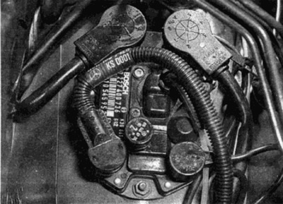
Pic. 6.5. Location of the electronic control unit
6. Disconnect the negative battery terminal.
7. Disconnect sockets from blocks of gauges of a cranked shaft and a detonation. Disconnect also the two multi-pin connectors, labeling each one in order to re-install correctly.
8. Disconnect the manifold vacuum hose from the fitting on top of the control box. Plug the nozzle so that dirt does not get into it.
9. Turn away nuts of fastening and pull out the control unit from a motor compartment.
Note: Thermally conductive paste has been applied to the bottom of the control box to improve cooling - try not to stain the surrounding parts with paste. Do not remove the protective layer.
Installation
10. Installation is carried out in the reverse order. If the contact paste layer is dirty or has hardened over time, purchase the required amount of paste from a Mercedes-Benz dealer and reapply. Check that the protective layer is correctly applied.
Coolant temperature sensor
11. Where provided, the ignition system and the fuel injection system have one common coolant temperature sensor - refer to the information given in the relevant part Chapters 4B (see fig. 6.11).
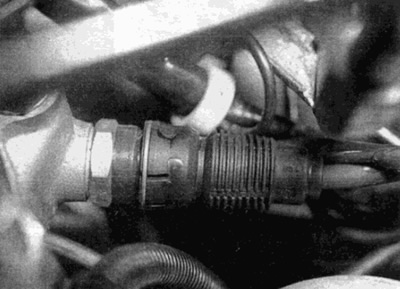
Pic. 6.11. coolant temperature sensor
Throttle position sensor
12. The ignition system has one throttle position sensor common with the power supply system - refer to the information given in the relevant part Chapters 4B.
TDC position sensor
13. The TDC sensor is located on a bracket above the crankshaft vibration damper at the front of the engine. Mounting the sensor with the bracket to the vibration damper is critical to the operation of the ignition system and requires complex installation steps. For this reason, this work is recommended to be carried out at a service station.